Chasing down losses in power delivery networks

Introduction
In the world of gambling, the worst thing is to chase losses, risking your shirt and worse. In power delivery network design, you are gambling with your job if you don’t. Every watt dissipated unnecessarily is a dollar and environmental cost, multiplying up with its increased cooling overhead.
Current produces dissipation in resistance, so, as with your utility AC supply, distribution at high voltage/low current is the way to go. For example, the recent trend toward increasing bus voltage in server blades from 12 V to 48 V reduces current by a quarter, and power lost in connection resistance by a useful 16x, due to that handy ’square law’ - that’s if the PCB designers don’t steal your gains with thinner tracks.
GPU current draw can peak at over 1000 A in AI applications
High currents right at the end load are inevitable though, with latest GPUs, FPGAs and CPUs in some cases gulping down over 1000 A, but at a fraction of a volt. So, although we can sneak tracks around at 48 V with maybe 15 A rating for this power level, we still need Point of Load (PoL) converters to generate the low voltage.
A traditional difficulty is that conversion tends to be less efficient for non-isolated DC/DCs such as PoLs with high input to output voltage ratios, as shown in the figure below. As a consequence, a second intermediate bus might be used at say 5 V or 12 V, but we do then have more converters with potentially more losses. However, an examination of the conversion efficiency curves of DC/DCs might show that there is a ‘sweet spot’ where multiple stages with lower conversion ratios can be as efficient as a single stage. More converters are a higher cost, but this is offset by savings in cooling systems if overall efficiency is higher.
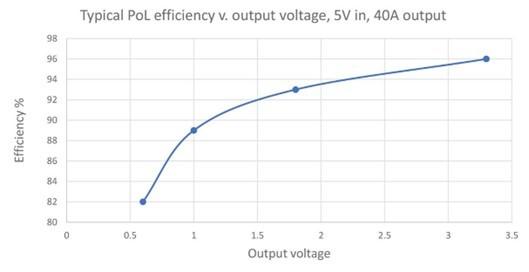
Picture 1: A DC/DCs efficiency can vary strongly with voltage conversion ratio
We shouldn’t get too hung up on % efficiency values though – it’s power dissipated that matters. For example, although the efficiency in the graph above varies widely, these figures are for a converter delivering 40 A, or 24 W at 0.6 V and 132 W at 3.3 V. Actual losses are then largely the same in each case, between 4.5 and 5.5 W.
Milliohm connections are far too high
Serious power dissipation occurs at the load, in the IC and to a lesser extent in the adjacent PoL. With our 1000 A+ peaks, connection resistances must be very low to avoid unacceptable voltage drops and significant extra power loss. If the PoL is placed on the PCB adjacent to the load, connection resistance could easily be close to a milliohm total, even with thick traces that anyway block data lines. This would produce a wholly unworkable 1 V drop and 1 kW peak dissipation in connections, with our 1000 A draw.
Another problem is connection inductance – latest server applications such as machine learning for AI tend to have high peak load demands, where GPU current draw can ramp up and down rapidly. If a 100 A step occurs for example within 1 ms, it would take only about 100 nH to cause a 10 mV voltage step. This value of inductance is only a few centimeters of total tracking, go and return.
The aim for best performance is to get the final PoL converter as close as possible to the load and this is best done with the ‘Vertical Power Delivery’ (VPD) approach championed by Flex Power Modules. Here, a customized PoL is fitted on the PCB bottom-side, directly underneath the load IC with a pin out that matches the target IC solder ball pattern, for the shortest connections. Now, connection resistance can be around 10 µΩ and inductance a few nH, producing acceptable voltage variation and dissipation.
Coping with 0% efficiency
PoL designers work hard to push conversion efficiency ever closer to 100% but with VPD, the DC/DC is now immediately next to the load which is 0% (electrically) efficient – all the input power, perhaps half a kilowatt, is turned into heat in the chip. Cooling is therefore a major consideration and the DC/DC must integrate with the IC cooling system, typically a ‘Direct to Chip’ or D2C arrangement with a cold-plate heat exchanger with liquid coolant.
Putting the odds in your favor
Power system design in high performance computing need not be a gamble; new approaches to DC/DC conversion architectures such as vertical power delivery allow an optimized solution aided by the close technical support and guidance of Flex Power Modules.