Designing power electronics with software

These software suites are naturally tailored to a particular manufacturer’s devices, but share a significant amount of functionality.
While configuring individual modules is clearly important to getting any system running, designers need a complete overview of the whole power system and how the modules are interacting to understand any issues that need to be addressed. Modern power development software recognises this and provides advanced functionality that will support the process from prototype to production.
Software is generally run on a host PC and communicates bidirectionally with the power system via a common bus such as PMBus. USB adapters are available for this purpose, enabling rapid and reliable connections. Examples include TI's USB-TO-GPIO2 adapter.
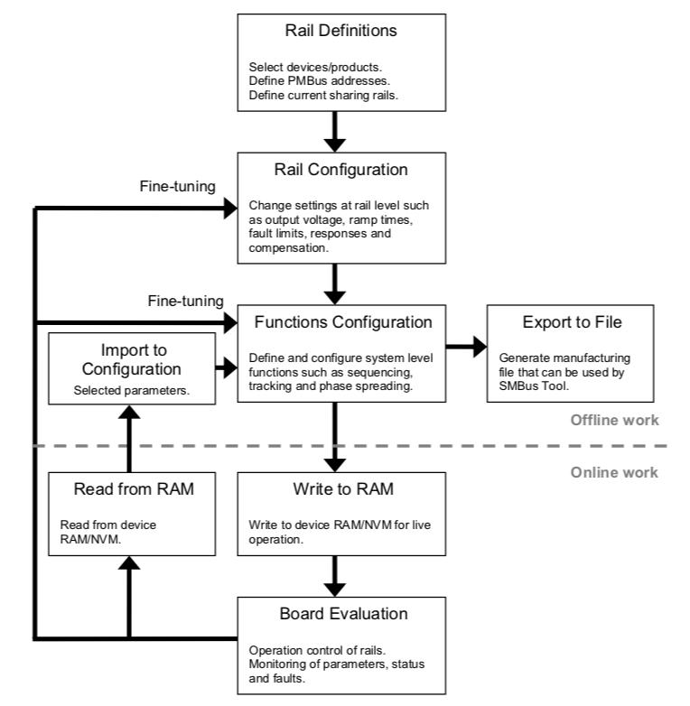
Figure 1: Power design software typically supports the design cycle from prototype to production
Most software works on the basis of a ‘project’, and the first step for designers is to establish the project as a file on the PC, using the power design software. The first step in the workflow is to build the system by selecting each of the devices within it. This work is all completed ‘offline’, and devices are selected from a manufacturer-supplied library that is embedded within the software.
Given the vast number of products available from most manufacturers, a product search function is usually available. This will allow search by part number if this is already known, but other searches such as product type, output voltage/power or feature/function as well as physical device size are also often available. Regularly updating the software will ensure that all of the latest devices are available to be selected.
The next step is to use the software to establish the basic parameters of the system – this would include setting up the PMBus addresses and definitions of all of the voltage rails in the system. Designers will then use the software to further configure each rail, defining parameters such as the voltage, ramp times, fault parameters and more – depending on the capabilities of the module(s) that are powering each individual rail. For more sophisticated systems that comprise fully featured modules, the final part of the set-up is to configure system-level functionality such as voltage rail sequencing, tracking and phase spreading.
All of the work to this point has been completed offline and no PMBus connection is required, nor is any hardware or soldering irons. At this stage, it is possible to create a system configuration file that can be used to configure the devices/system in a manufacturing environment.
However, at this point designers generally opt to test the configuration in hardware. Using the communication bus (usually PMBus), all of the configuration information is sent to the modules and stored in onboard non-volatile memory (NVM).
Hardware evaluation and monitoring
Modern power design software generally offers far more sophistication and functionality than simply configuring the modules and system parameters. As designers run the system under power to check and tweak the operation, most software will allow detailed monitoring of performance.
At the most basic level, voltage rails can be monitored, but there is far more data generally available from power modules. Depending on the software package and modules being used, designers will be able to monitor parameters such as voltage and current at multiple points as well as module temperature, duty cycle and operating frequency. These parameters can be monitored continuously and advanced software will be able to give a graphical representation of each parameter against time, with selectable sampling intervals and monitoring duration, enabling designers to understand exactly how the system is operating.
Many power modules contain circuitry to detect faults such as over-voltage, over-current, over-temperature and more. Power design software is also able to monitor these alarms and faults and, using the parametric traces, designers can understand the exact system condition immediately preceding the fault condition.
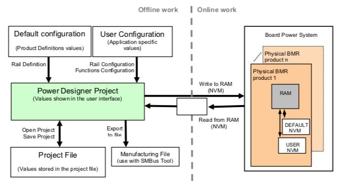
Figure 2: Configuration can be sent and read back from physical hardware
Design and development is by its very nature an iterative process, and power design software recognises the need to adjust and adapt designs for optimum performance. Designers are able to read back values stored in RAM on the modules and then make configuration adjustments within the software before reloading the adjusted parameters to the modules and continuing the analysis of the physical hardware.
Once the development phase is complete and the design has stabilised, the software allows the configuration to be written to a final configuration file that can be used within the manufacturing environment.
Thermal analysis and evaluation
Until recently, the only significant functionality not present in power design software was the ability to perform detailed thermal simulation of the design. Given the performance and power density typically required in today’s power systems, simulation and analysis can ensure that there is sufficient design margin under all operating conditions.
Earlier this year, Flex Power Modules recently launched V3.0 of its Flex Power Designer software which uniquely contains this thermal analysis as standard. Armed with this new feature, designers are able to fully simulate the thermal performance of their designs and see the effects of altering key parameters such as ambient temperature, PCB copper thickness and forced air cooling.
The simulation tool provides a graphical output showing the dependencies between multiple parameters, such as temperature against output current, input voltage or fan speed. Based on this information, designers are able to confirm that their design meets any derating guidelines and complies with safety agency requirements, thereby reducing the risk of weaknesses in the design.