Harnessing liquid cooling in AI data centers
Introduction
This article discusses the necessity and benefits of liquid cooling in AI data centers, focusing on the challenges posed by high-power AI servers and the advantages of Vertical Power Module (VPM) systems. It covers different cooling methodologies, practical comparisons of cooling methods, and the implications for associated DC/DC converters.
When a market is growing explosively, such as that for AI servers, the potential size is difficult to predict. Nevertheless, analysts ‘Research and Markets’ estimate that the segment will quadruple in value to over US$50B by 2029 [1]. Although currently representing just 10-15% of the total data center market, servers geared towards AI applications are very power-hungry. The latest GPUs utilized for AI servers, such as the Nvidia GB200 (which is a combination of two Blackwell GPUs and one Grace CPU), dissipate over 1kW continuously and over 2.5kW peak. This is a significant leap from the earlier generation H100 Nvidia Core GPU, which operated at 700W and with only 20% of the processing performance.
Processors need the provision of local power rails from DC/DC converters, which need to be placed as close as possible to avoid static and dynamic voltage drops across connections. However, at the increased power levels seen in AI servers, converters placed laterally around the processors are just not close enough and additionally block access to signal routing. A relatively new approach developed by DC/DC converter manufacturers such as Flex Power Modules [2] is a Vertical Power Module (VPM) DC/DC placed immediately under the processor on the bottom side of the PCB (Figure 1). Now, the multi-channel DC/DC is in the optimum position electrically to transfer power with minimum PDN (Power Delivery Network) losses.
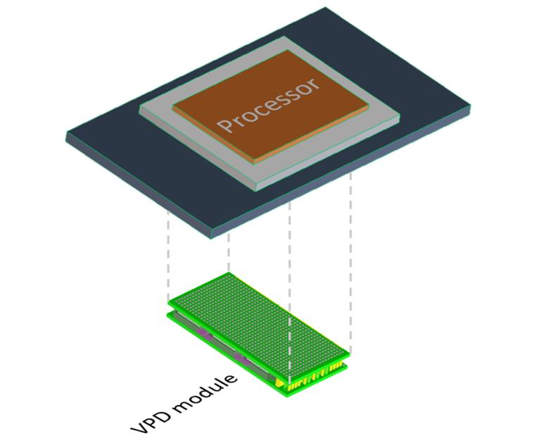
Figure 1: Vertical Power Delivery to a processor
In practice, a VPM is designed for a specific processor and server arrangement, as its pin-out must match that of the processor to allow easy routing of PCB traces. For best performance, a VPM should be included in thermal modeling and ideally liquid-cooled on the bottom side of the PCB with its cold plate. The low-profile format of the VPM device with its large surface area matches well mechanically with the ‘direct to chip’ liquid cooling of the processor through a cold plate, which would be used at AI server power levels. This compares with the more traditional lateral approach to placement of DC/DCs which are typically designed for minimum footprint area and forced air cooling. This all means that the VPM will be considered early in the system specification stage and can be included in the design of the cold-plate cooling arrangements.
The necessity for liquid versus convection cooling can be gauged by the measure of power dissipation per square centimeter of processor footprint, with about 50W/cm2 being a suggested breakpoint, depending on the rack size (Figure 2). At lower power densities, forced air cooling has been the norm, but finned heatsinks are large and the hot air on the exhaust side might blow across other components with adverse effects on reliability. This can be mitigated if the processor and heatsink are placed close to the air exit point in the server blade enclosure, but this is an undesirable constraint on the board design.
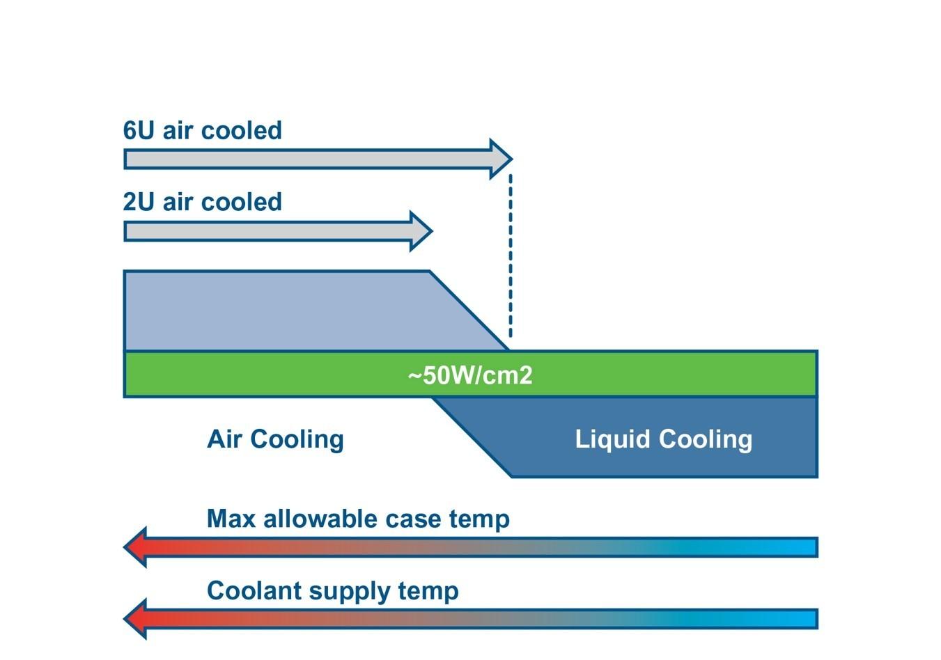
Figure 2: Liquid cooling of chips is needed above approximately 50W/cm2 dissipation
Liquid cooling is therefore a technical advantage at any power level, but it cannot be a ‘bolt-on’ upgrade. An optimum system requires a ground-up design approach that also considers other heat-generating components, such as the DC/DC converters supplying local power rails.
Cooling methodologies
So, what makes liquid cooling so much better? The advantages include better efficiency of heat energy transport, leading to smaller size, lower system energy consumption and reduced operating costs. Liquid cooling also eliminates the need for at least some of the noisy and relatively unreliable fans close to the load, although a centralized heat exchanger is still necessary to remove heat from the fluid. This is typically achieved by forced air cooling to the environment or to another piped water loop, which could be used for community heating, for example. The downsides of liquid cooling are higher installed cost, a consequent delayed return on investment, and potentially lower system availability on failure – as liquid cooling is more centralized compared with individual server fans.
A closed loop ‘hybrid’ liquid cooling arrangement is shown in Figure 3, where heat is transferred from the processor to a cold plate incorporating water channels. The arrangement is called Direct-to-Chip cooling, and the size of the plate is typically the same footprint as the device to be cooled. Indeed, it only needs to be of a sufficient thickness to accommodate the channels. This is a ‘single-phase’ arrangement where the coolant, normally water, is contained and remains in a liquid state continuously. This technique gives a dramatic improvement in heat removal capacity compared with forced air cooling as we will quantify later, but a further incremental benefit can be achieved by using a fluorocarbon-based liquid with around 10x better thermal conductivity. Additionally, if this heats to its boiling point of around 50°C, in a two-phase arrangement, the latent heat of evaporation of the fluorocarbon typically used allows around 100x better heat absorption per unit volume of liquid than a single-phase arrangement. An advantage is also that dielectric coolant is far less damaging to components than water if there is a leak, but a two-phase arrangement is relatively more expensive to implement. In practice, the thermal interface material between the processor and cold plate becomes a limiting factor making the single-phase arrangement a good solution overall.
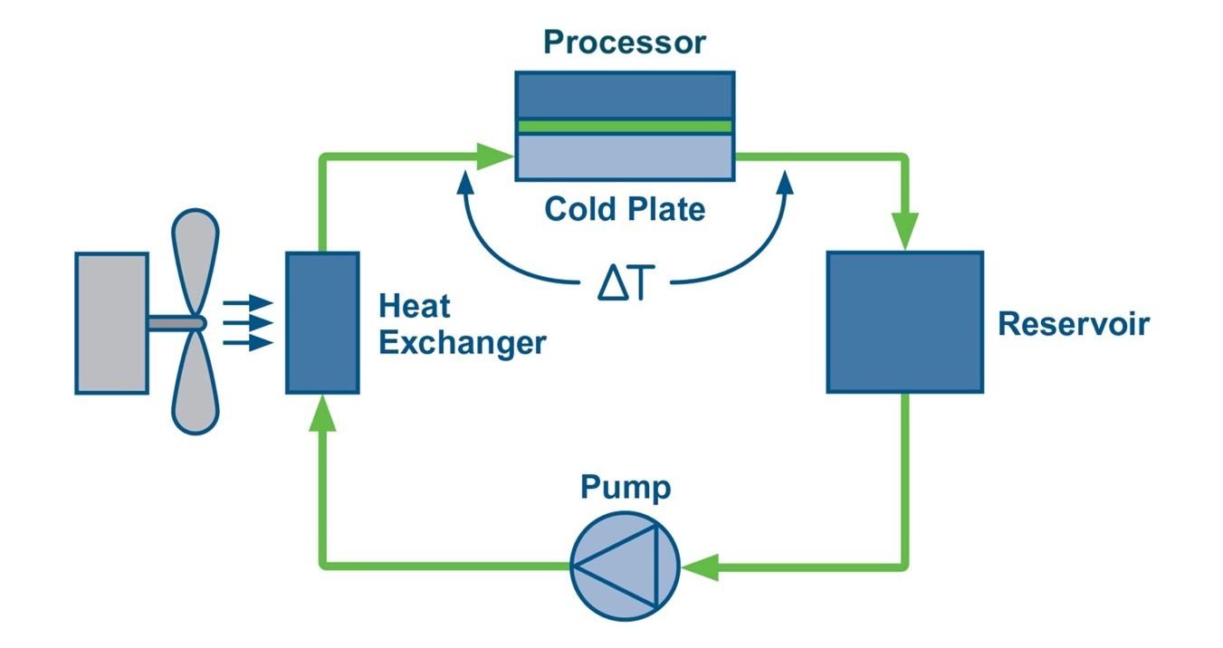
Figure 3: Diagram shows a single-phase, water based direct-to-chip liquid cooling system with liquid-to-air heat exchanger
Immersion cooling is also a possibility, where the entire electronic system is submerged in an open bath of dielectric liquid. This can be extremely effective, with the liquid circulating to a heat exchanger, such as a cooling tower. However, there is some understandable reluctance to use immersion cooling due to environmental concerns, the possibility of leaks, and the cooling being a single point of failure for an entire rack. The fluid used is non-conductive but has a dielectric constant typically about twice that of air, which doubles stray capacitance through the liquid and may impact high-frequency signal lines. The system can be single or two-phase.
Practical comparisons
The main metric of relative performance of air and liquid cooling is heat capacity, sometimes referred to as thermal capacity. This is the power that heats 1kg of the medium by 1°C in one second. The value for water is 4.2kJ/kg while air is 1.0kJ/kg. 1kg of air is about 0.85m3 while 1kg of water is about 1 liter or 0.001m3 so 3600x more volume of air than water is required to ‘move’ the same amount of heat.
To compare the relative performance of cooling methods, consider a processor dissipating, say, 1kW (Q) with a surface temperature limit of 80°C in a maximum ambient of 50°C and with a fast airflow of 5m/s. This processor would need an attached heatsink volume, V, of about 2,700cm3, from the simplistic relationship: V=(Q.RV)/ΔT [3]. This assumes that the 5m/s airflow gives a volumetric thermal resistance (RV) for the heatsink of 80 cm3 °C/W.
A heatsink of this size, about a 14cm cube, is clearly impractical. The size could be reduced, but only with the increased hardware and energy costs to lower the ambient temperature or allow the processor temperature to rise, leading to reliability concerns, as the die temperature would be higher still. Heat extracted is blown across other components and exhausted locally to the server rack, where air is then in turn cooled by the date center’s air conditioning system. An additional constraint is that, for a temperature rise of the air from inlet to outlet of say 20°C and 1kW power dissipated, an air flow rate of about 40 liters per second is needed and at 5m/s, this requires a minimum area for the air path of around 8cm2 which must be maintained through the server blade housing.
In contrast, in a liquid cooled system, a cold plate can have a thermal resistance to the liquid as low as 0.01°C/W. With 1kW and a chip surface temperature limit of 80°C, the water temperature should therefore rise to no more than 70°C, assuming no other routes for the heat to dissipate. For an inlet water temperature of, say, 25°C, we can calculate the required Mass Flow Rate (MFR) of water from MFR = Q/ΔT.c [4], where c is the specific heat of water (4.2kJ/kg°C). This calculates to a MFR of 0.005 kg/second or 5cm3/second which is only about 6.4cm/second flow rate through a 1cm diameter pipe, which is easily achieved.
The hot water passes to a heat exchanger, typically a finned radiator, but this can be relatively small and efficient as the coolant pipes can be evenly distributed, unlike in a processor heatsink where the heat source is concentrated in a small area.
Conclusion
With the enormous power levels seen in latest AI-targeted processors, liquid cooling has become a necessity. The kilowatts dissipated also have implications for the positioning and cooling of associated DC/DC converters, and these should be included in the overall thermal design.
(first published in Power Electronics News)
References
[1] https://www.researchandmarkets.com/report/artificial-intelligence-server
[2] https://flexpowermodules.com
[3] https://celsiainc.com/resource...
[4] Simons, R., Estimating Temperatures in a Water-to-Air Hybrid Cooling System, Electronics Cooling May 2002