Improving buck regulator transient response with TLVR
Introduction
Power requirements for CPUs and GPUs in modern data centers have dramatically increased recently, especially with the new intensive AI applications being run. For example, a device dissipation of over 2kW at 1000A+ peak current is envisaged for latest GPUs, such as the Nvidia GB200. At the same time, the current drawn by the ICs fluctuates rapidly between idle and full power as processes throttle up and down.
Multi-phase bucks are the practical solution at high power
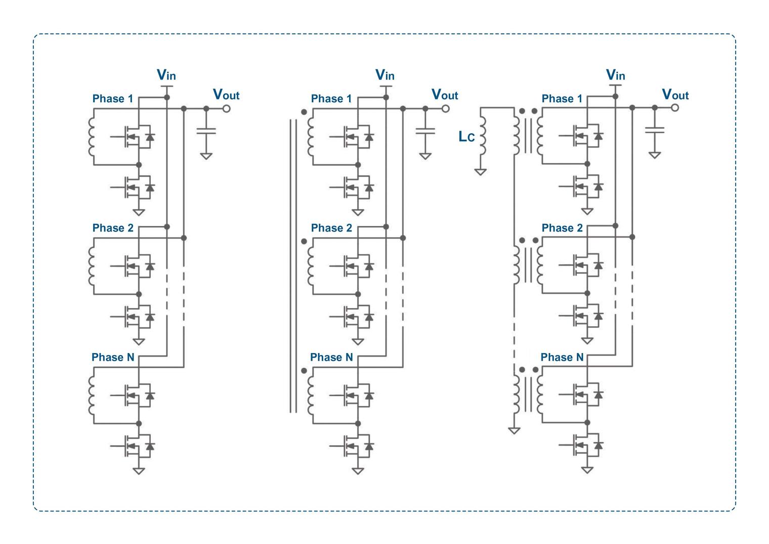
Buck regulators, typically supplied from 12V, are used to generate the power rail for the ICs, which is now around 0.6V. At the power levels, interleaved multi-phase techniques (see Figure 1 on the left), are essential. They divide the regulator dissipation between multiple power stages, which has the beneficial side effect of cancelling output ripple current.
This, in turn, reduces the output ripple voltage for given capacitor sizes and lower dissipation in the capacitor ESRs. To achieve further efficiency gains, the inductors in the multi-phase buck can be coupled together as one magnetic structure (see Figure 2 in the middle). This effectively introduces ripple current cancellation within the inductors, switches, and PCB traces, resulting in lower dissipation and potentially smaller component sizes.
However, there are tradeoffs: the degree of cancellation depends on the duty cycle. Additionally, although the ripple current has a lower RMS value, it has a high component at a frequency of N x F, where F is the phase switching frequency and N is the number of phases. This can increase core and potentially capacitor losses. In practice, the multiphase coupled inductor approach is often used to reduce the switching frequency for an acceptable ripple current, thereby lowering switch dynamic losses. Alternatively, the frequency can be kept high, but the inductor values can be reduced for an acceptable ripple current, leading to faster load transient response and higher inductor saturation current for the same core size. For example, with four coupled phases, the magnetic size can be reduced by about 4x, and the inductor current slew rate with load transients can be about 6x better, with correspondingly lower voltage excursion. However, with a higher number of interleaved phases, a single magnetic structure becomes impractically complex. Therefore, coupling is sometimes divided into smaller groups of phases, resulting in less overall advantage.
The next innovation – the TLVR
Another recent approach to improving transient load performance further has been the Trans-Inductor Voltage Regulator, or TLVR. This is shown in Figure 1 (right).
Figure 1: The evolution of multiphase buck regulators – uncoupled (left,) coupled (center) and the TLVR (right)
In the TLVR, discrete inductors are used, each typically with a 1:1 secondary winding. All these windings are connected in series, with their ends grounded through an inductor Lc, which includes a discrete component and the sum of all leakage inductances of the transformers. The transformers function as voltage converters, so the current in the secondary is determined by the load (the compensation inductor Lc) and the duty cycle. At specific duty cycles, the reflected voltages cancel out, specifically when D=1/N for an N-phase converter. When a load transient occurs and the output starts to drop, the feedback control increases the pulse duration (duty cycle) of the phase conducting at that moment. Due to transformer action, the associated transformer secondary experiences a longer voltage pulse T, increasing the secondary peak current according to I=ET/Lc. This current, however, flows through all the transformer secondaries and reflects the same current increase in each of the primaries. The primaries are in parallel, so the current fed to the output is the coupled value multiplied by the number of phases, effectively amplifying the increased current from the conducting phase by N. This effect provides an increased current supply in a given time, i.e., higher di/dt, leading to faster reaction to transient loads with less voltage overshoot and undershoot. Figure 2 shows results achieved with a 12-phase TLVR at 750kHz, Lc=100nH, with a 6mF output capacitance. The load transient ranges from 100 to 500A at 2000A/µs, identified in the source as approximately a 5x improvement over a conventional multi-phase buck.
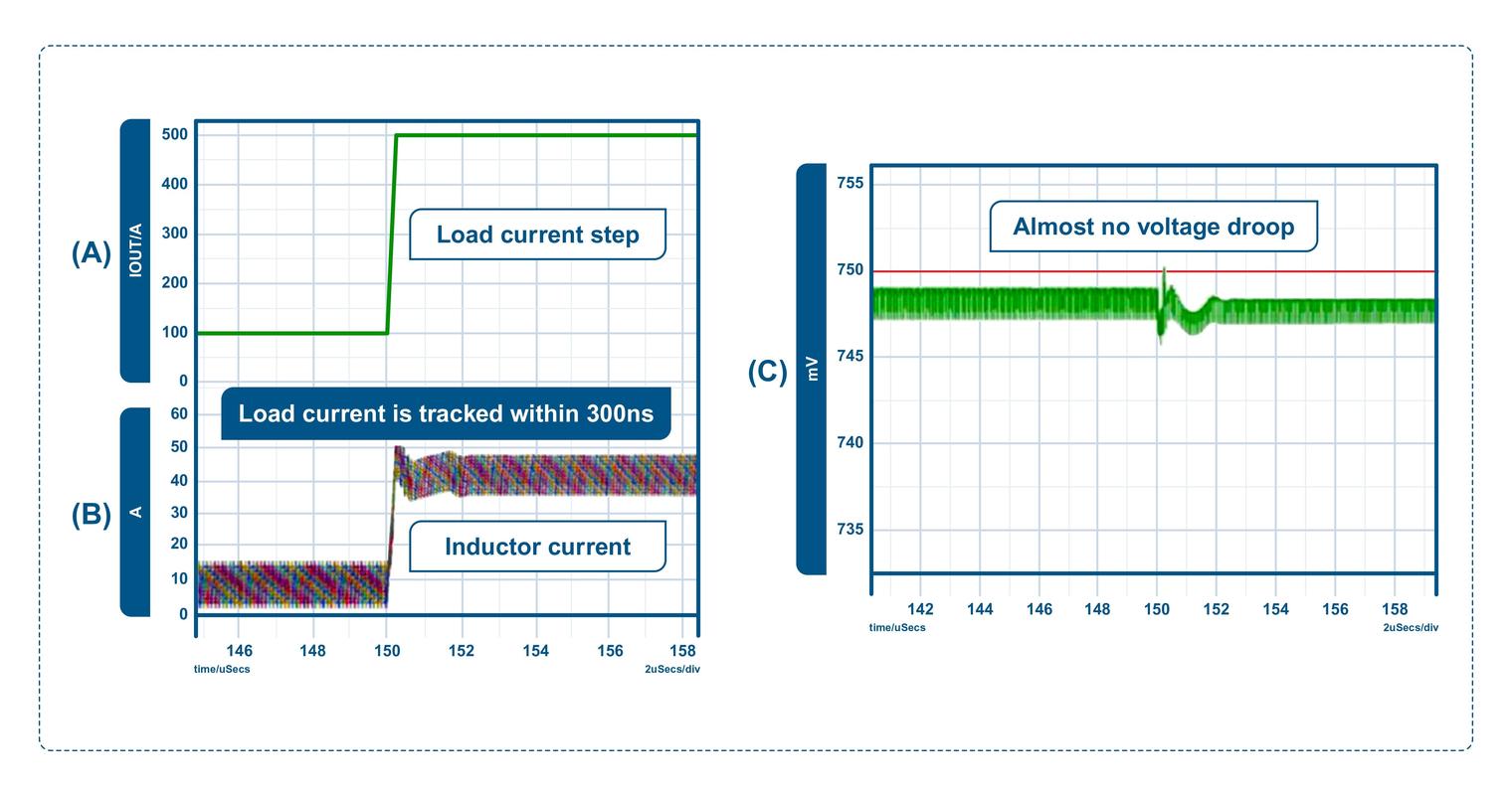
Figure 2: Results achieved with a 12-phase TLVR with a 400A load step. The droop is less than 5mV[1]
TLVR limitations
Unlike the coupled inductor approach, the TLVR does not cancel ripple in the main inductors but actually increases it with the reflected ripple through Lc, resulting in higher peak values than those seen with a basic multi-phase buck. This necessitates larger output capacitor sizes to maintain the same ripple voltage. Additionally, the main inductors must be rated to avoid saturation at the higher ripple current under steady-state conditions, making them either larger or requiring lower inductance, which in turn increases ripple current for the same operating frequency. Reducing inductance to avoid saturation typically means a larger core gap and reduced coupling between windings in a TLVR, compromising its effectiveness. Therefore, detailed analysis is needed to find an optimal operating point for the best efficiency, transient response, and magnetics size and cost. The TLVR performance also closely depends on the steady-state duty cycle, set by the input/output voltage ratio, and the number of phases.
Across all operating points the benefits of the TLVR vary, so Lc must be chosen carefully to allow the desired extra coupled current for improved transient response given number of phases and natural duty cycle variations that are compensating for static volt drops at different currents. Clearly, the TLVR would not be ideal for buck converters that need a significant output voltage adjustment range with corresponding duty cycle variation. Another minor concern is that the secondary winding voltages, approximately Vin peak to peak, are in series and therefore add. For large numbers of phases this could be significant – around 288V total for 12V input and 24 phases, for example. This is far over the value regarded as ‘safe’ and therefore affects isolation ratings, distances and product certification. In the TLVR, there is also the cost and space overhead for the extra discrete component Lc.
Summary
The TLVR approach has the potential to provide an improved combination of transient response, efficiency, size and cost in multi-phase buck regulators, but only if all components and operating conditions are considered and tuned for an optimum result.
References:
[1] n/a, "Fast multi-phase trans-inductor voltage regulator", Technical Disclosure Commons, (May 09, 2019) https://www.tdcommons.org/dpub...