Measuring conducted EMI on DC/DC converter inputs

A DC/DC converter creating noise within its supply isn’t desirable, but how much is too much and how do we measure it anyway? Unlike AC/DC converters, there are no statutory standards for an acceptable level or measurement setup, and, in any case, the noise amplitude and spectrum will vary with grounding arrangements and whether the DC/DC converter is isolated or not.
We see DC/DC manufacturers quoting compliance with standards such as EN 55032, CISPR 32 and FCC Part 15 with Class A and B limits, but these refer to maximum levels allowed on an AC distribution network, which is not relevant to DC/DC converter input lines. The levels that a system with internal DC/DC converters can stand are highly dependent on the immunity of other devices, if any, connected to the DC input line and the physical layout. For example, conducted noise on lengthy internal DC interconnections can cause external radiated EMI which is subject to statutory standards such as those called up in the European EMC directive.
It can therefore be worthwhile to make measurements according to a standard such as EN 55032, if only as a subjective measure and a way to compare competing products. Key to the measurement for AC or DC input devices is the insertion of a line impedance stabilization network (LISN) in the input line. This is intended to isolate variations in the supply impedance so that measurements are consistent in different electrical environments.
LISNs come in different varieties, typically ‘V’ and ‘Delta’ types. The arrangement for a V-LISN is shown in the figure for the general case, where the DC/DC converter ground is remote, so noise is measured in both the positive and negative lines. Of course, the input may not be grounded at all and if the DC/DC converter is isolated, its output may or may not be grounded in the actual application, and this makes a real difference to the measured levels.
Additionally, LISNs are also not the same. CISPR 16-1-2 gives examples but it’s not always clear which to use for different DC/DC applications. AC input devices usually use LISNs with 50 µH chokes whereas 5µH is more common with DC/DC converters and is specifically required in automotive EMI testing (according to CISPR 25, for example).
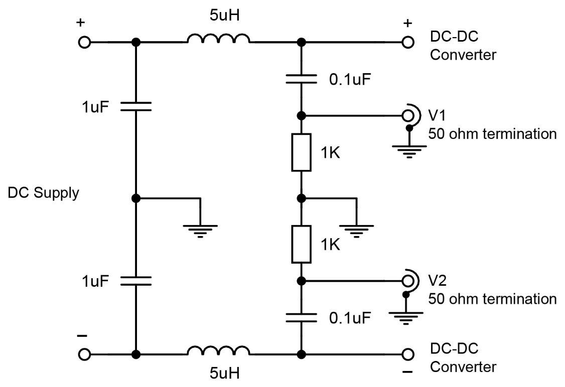
Picture 1: A V-LISN with typical values used with DC/DC converters
At this point we need to differentiate between differential-mode and common-mode noise. Differential mode is the voltage (or current) between the input lines and common mode is the voltage (or current) between both input lines (tied together) and ground. However, ground may not be well defined for a DC/DC converter. For an AC/DC, the V-LISN signal output delivers a voltage equal to the common mode value plus half of the differential mode, whereas the Delta LISN separates the modes for independent measurement. With a DC/DC converter, the value depends on whether and where a ground is connected. If it is at the DC/DC converter input return line, there is no common mode noise at the input by definition. If ground is upstream of the LISN, the measured value will be higher and if the DC/DC converter is isolated and its output grounded, the noise measured will be even less determinate. Typically, what matters at the system level is the DC/DC converter differential mode noise, so this has to be extracted from the LISN measurement, taking account of the grounding location.
Standards such as CISPR 25 also specify noise measurement as a current out of the DC/DC converter input terminals. This is potentially more useful as it does not rely on another point as a reference, as in a voltage measurement. A LISN is still needed, though, as the current depends on the impedance of the circuit upstream of the DC/DC converter. Low power DC/DC converters often have their input noise specified this way but just with a series inductor rather than a LISN. The inductor value is arbitrarily specified among manufacturers, and its self-resonance, inductance variation, and resistance are unspecified, making comparative results unreliable. At low power, the noise current is usually just stated as an RMS level without a specified measurement bandwidth, and is typically a very small value, whereas peak levels can be much higher across a wide spectrum of frequencies, again making the measurement less meaningful.
Conducted input noise from DC/DC converters is an important parameter and can cause erratic system operation, so should be measured and minimized. However, what level is acceptable can only be determined system-by-system and comparative measurements should use the same grounding arrangements and should not be assumed to be indicative of the levels present in the final application. At worst, an unnecessarily large filter might be selected, which can affect converter stability and introduce its own problems such as resonances causing noise peaking, and induced transient voltages during load steps.
Contact us for expert advice or if you want to discuss EMI filter design with us.