Processor power sequencing

Abstract
Processors, FPGAs, DSPs and other devices have multiple power rails which must start up and shut down in the right sequence and at correct rates to avoid latch-up, functional anomalies or even damage. Digitally controlled point-of-load DC-DC converters are commonly used to provide the power rails with appropriate sequencing and timing in firmware, or programmed through a communications bus. This article describes the typical schemes used.
Article
Providing power to ICs such as processors, FPGAs, DSPs, ASICs and DDR RAM is not a trivial exercise. There are usually several power rails required at various voltages, from 3.3V down to sub-1V. Each rail must be stable with load variation and environmental changes both statically and dynamically, and with load current steps that swing dramatically from sleep to active mode and back again. The voltage might need to be actively controlled as well, with techniques such as adaptive voltage scaling employed to minimise power consumption depending on processor workload, or margining to test the limits of functionality.
An additional consideration is how the voltage rails rise and fall at start-up and shut-down in terms of sequencing, ramp rates and delay after an enable/disable command. If you get it incorrect there are various potential dangers. A simple limitation is inrush current; the IC will often take a peak current of several times the normal running value as internal capacitances are charged and logic settles. Each rail will also have external capacitance, typically several hundred microfarads, to provide transient energy in normal operation – but these start discharged and add to the inrush current. If all rails ramp up together, the upstream common supply may be overloaded by the surge current demand and enter a current limit mode, reducing its voltage. There is then a real danger of voltages from the separate rail regulators dipping as they try to start, making the rise non-monotonic and preventing correct IC start-up. Sequencing of the rails spreads the inrush energy over time, so the peak demand on the upstream power supply is lower. With power rails rising in an uncontrolled way, there is also the possibility of momentary internal bus-contention issues as tri-state buffer biasing settles, which again could prevent correct initialisation. A more insidious problem can occur when substrate or ESD protection diodes are forward-biased by incorrect sequencing. If the 2.5V rail in Figure 1, for example, came up before the 3.3V rail, ESD protection diode D1 would pass current into C1 on the 3.3V rail, perhaps damaging the diode. This ‘pre-bias’ on 3.3V rail could also cause start-up problems for the 3.3V regulator. Even with correct sequencing, IC manufacturers will often set maximum and minimum ramp rates to supply voltages on start-up and shut-down for correct operation.
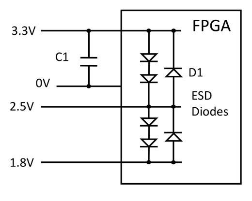
Figure 1: ESD diodes provide a 'sneak' current path on start-up
Modern point-of-load (PoL) regulators are designed specifically to generate the rail voltages needed, and most recent types will have digital control – making them programmable both in firmware and remotely, typically through an I2C PMBus connection. Along with comprehensive monitoring, output voltage can be set, as well as start-up delay and ramp rates. The devices will have at least an enable pin, allowing sequencing under external or time-based control, but there may also be more intelligent modes such as event-based, general communication bus (GCB) control and voltage tracking.
Time-based sequencing
Perhaps the simplest scheme, time-based sequencing relies on pre-programmed start-up/shut-down delays and rise/fall ramp rates in individual PoL converters with a common enable or control line that initiates the sequence for all converters together. The accuracy of timings relies on the specification of the individual converters, and sufficient margin must be allowed for, so that the correct sequence is always maintained. Digital control PoL converter manufacturers often provide supporting software to pre-configure their converters with the chosen timings, which is then fixed in firmware. The GUI for the software will typically show the programmed values graphically (Figure 2).
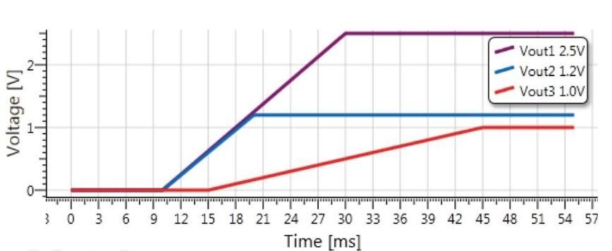
Figure 2: Typical graphical output of PoL design software for time-based sequencing (FPD)
Event-based sequencing
This scheme ensures a strict sequence of start-up/shut-down by linking the ‘power good’ signal from a controller converter to the enable input of the next, which in turn enables a further converter (Figure 3). Rise and fall times and start-up/shut-down delays are pre-programmed into each converter, as in the time-based scheme. The downside of the scheme is that the sequence is hard-wired and would require hardware changes to alter the order.
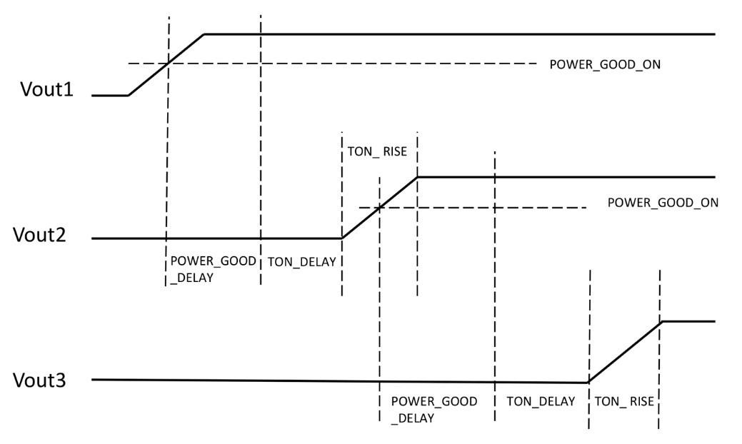
Figure 3: Event-based sequencing
GCB sequencing
For a high level of flexibility, GCB sequencing can be used. Here each PoL converter can communicate with others in a group through a dedicated serial General Communications Bus to set any programmed sequence and timing, which can then be altered without any hardware changes through PMBus commands. Enable pins of devices can be paralleled to give an overall start/stop command through either a CTRL signal or PMBus control, and up to 32 PoL converters can be connected this way, covering all realistic scenarios. This additionally allows simultaneous functionality such as fault spreading, phase add/drop, broadcast margin and broadcast enable, along with monitoring of temperature, load current and any fault occurrences.
Voltage tracking
Sometimes it is the relative value of IC start-up and shut-down voltages which is important, with limits to differences between rails rather than absolute values. This is addressed with a voltage-tracking mode where the output voltage from a controller converter, typically the highest voltage, becomes the regulation reference for others in a group (Figure 4). Now controller and target voltages are locked, and rise and fall times are set by the controller. If the target needs to be a fixed-output fraction of the controller, so called ratio-metric tracking, this is achieved simply with a resistive voltage divider from the controller output feeding the target tracking control input. The PoL converters must be designed with a VTRACK input to directly control the output voltage.
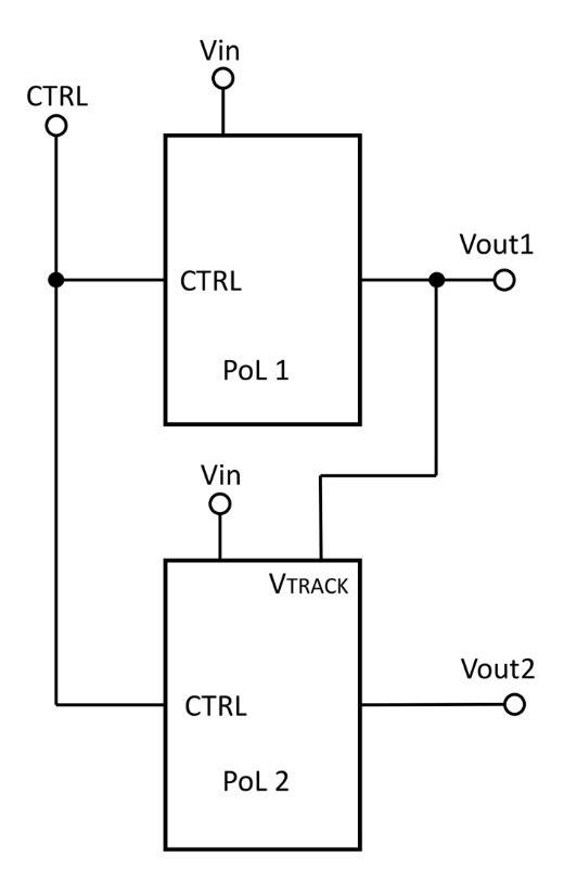
Figure 4: PoL converters in tracking mode
All of the sequencing modes, with control over delays and voltage ramp rates, are facilitated by the modern digital PoL with its complete flexibility and programmability. Companies such as Flex Power Modules are at the leading edge of the technology, with a range of PoL products along with its Flex Power Designer software and intuitive GUI, which makes set-up and simulation of performance easy, with automatic rule checking to ensure that valid parameters have been set.
Note: the common terms "master" and "slave" in this article have been replaced by "controller" and "target".