Intermediate bus voltage for AI processors

Introduction
AI is a technology that is rapidly pervading all aspects of society, from face cloning on social media to optimization of factory automation. The remarkable capabilities of AI are driven by significant advances in computing power within server farms, where processor transistor counts now reach hundreds of billions, resulting in chip power dissipation figures measured in kilowatts. However, there are challenges ahead for further progress — chip supply rails cannot be reduced much more to lower power consumption; heat extraction is a growing issue, and routing over 1,000 amps to a processor chip in the limited space available has become a major practical concern.
The intermediate bus approach
The final chip core voltage, now around 400mV to 900mV, generated from the incoming AC supply to the server farm is done in stages. Initially, it is often converted to 54VDC, which is practical for distribution around the server rack. This approach enhances electrical safety and keeps currents relatively low, allowing for reasonable cable sizing. DC/DC converters at the processors can then reduce the voltage directly to sub-1V. However, this large conversion ratio results in significant losses and occupies more real estate, therefore less practical at higher power levels. To address this, an intermediate bus is typically used, followed by a multi-phase Voltage Regulator Module (VRM) located close to the processor to minimize static and dynamic voltage drops under high load currents. A recent power electronics design trend even places this final conversion stage directly beneath the processor to provide ‘Vertical Power Delivery’.
There is now a choice to be made regarding which intermediate bus voltage to use, and determining the optimal value is not so straightforward as there are multiple factors to consider. The DC/DC Intermediate Bus Converter (IBC) generating the bus voltage is normally a ‘fixed ratio/unregulated’ converter for enhanced efficiency and simplicity. The most common ratios are of 4:1 and 8:1 which produce nominal voltages of 13.5VDC and 6.75VDC, respectively. But how do you decide which to choose?
4:1 or 8:1?
An obvious key difference between the two bus voltages is the output current rating: around 150A for 6.75VDC compared with 75A for 13.5V per kW of load. This means a 1st stage 4:1 IBC can be placed further away from the 2nd stage VRM converter without considerable distribution loss, freeing up space for processor GPIO, PCIe and memory routing. On the other hand, to avoid significant distribution losses due to 8:1 1st stage IBC they need to be placed near 2nd Stage VRM which may intervene in processor routing.
An input of 13.5V to the 2nd stage VRM is often an optimized value for the VRM and produces relatively lower conduction losses in its top-side switch as its duty cycle is lower than with 6.75V input, but the VRM also has relatively higher switching losses. These are proportional to input voltage, switching edge duration, power and frequency, so overall efficiency of the PoL, comparing 13.5V and 6.75V inputs may be little changed.
Perhaps a more significant issue is that a 4:1, 13.5V IBC requires twice the output inductance compared to an 8:1 IBC for the same ripple current and switch off-time (See figure below). The practical result is that for a compact IBC footprint, the inductor, which is already often the tallest component in many designs, will become even taller, potentially increasing the overall height from 5mm to 10mm. This can be problematic close to the processor, where high-power liquid cooling plates extend over adjacent components, requiring them to be low-profile. A 10mm-tall IBC may not fit on the rear side of the PC, restricting placement options.
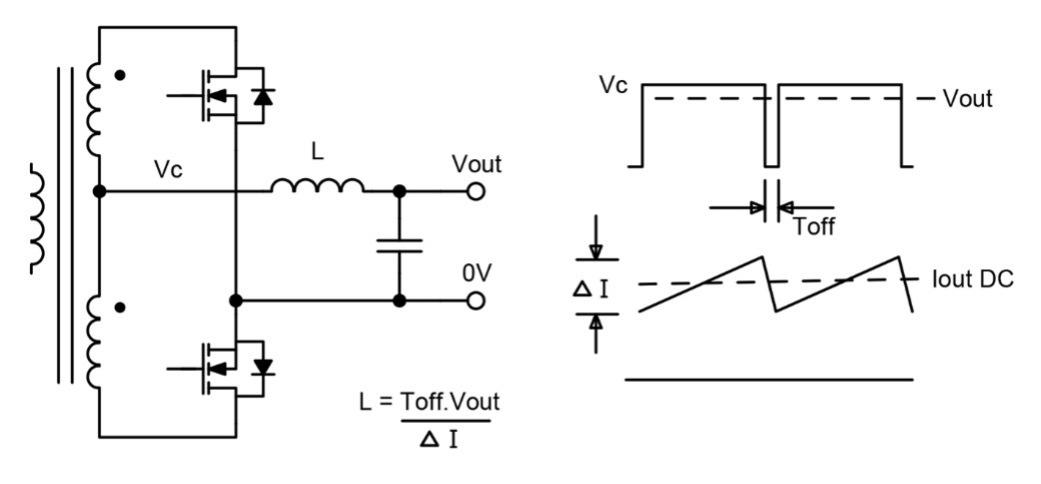
Figure 1: In the output stage of a ‘ratio’ IBC, inductor size for a given ripple current and off-time is proportional to output voltage
Other considerations
Of course, other conversion ratios, such as 5:1 and 6:1, are available and can be used to fine-tune performance. However, the more common ‘standard’ ratios of 4:1 and 8:1 tend to offer the best compatibility and wider range of DC/DC converter options.
Power conversion architectures are typically evaluated for overall end-to-end efficiency, and this is certainly an important factor when choosing an IBC. However, the actual power dissipated in the IBC and VRM is completely dwarfed by the load, which is typically 25 times larger and located nearby. For example, a processor dissipating 1kW might only cause the IBC to lose 20W. As an illustration, the Flex BMR315 5:1 IBC and BMR320 8:1 IBC have only a 0.3% efficiency difference at 400W output, representing just 1.7W difference which is hardly significant. Given the low dissipation in the IBC, it is typically manageable with standard system airflow, rather than needing to be integrated into complex liquid cooling setups required by the latest generation of CPUs.
Conclusion
When selecting the ideal IBC voltage conversion ratio, system designers should consider factors beyond just overall efficiency. Physical size, especially height, may become a deciding factor in the limited space available on today’s high performance AI server boards.