The benefits of hybrid regulated ratio topologies for IBCs
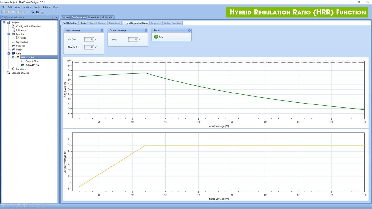
A third way for isolated IBCs
When designing the distributed power architecture for applications such as data centers, an isolated intermediate bus converter (IBC) might be used to take a nominal 48V or 54V input and generate a 10V to 12V bus for one or more downstream point-of-load (PoL) converters. In the past, there have been broadly two approaches – a simple fixed-ratio converter with unregulated output, or one with full regulation with fixed output.
Now, hybrid regulated ratio (HRR) converters have been developed to combine the advantages of both, switching seamlessly between each mode according to the input voltage. To fully understand the value of HRR, it is necessary to compare the operation of HRR, fixed-ratio and fixed-output converters and consider each in relation to typical operating conditions.
Background and operating principles
Recall that pulse width modulation (PWM) of a bridge-type switching power converter controls output voltage – longer switch on-times increase the average voltage passed to the output while shorter on-times reduce the average with an output filter smoothing the waveform to DC. Sensing output voltage, PWM can be used to compensate for varying input voltage, with the transformer turns ratio set to give close to 100% duty cycle at minimum input. Higher loads also increase duty cycle incrementally as the converter compensates for increased voltage drops at higher current. At near 100% duty cycle, little energy needs to be stored during the off-time in the output inductor, and input and output switching currents are close to continuous, with their average value close to the RMS value. In contrast, at low duty cycles, significant energy must be stored and released each switching cycle, and current waveforms have high ratios of peak to average with consequently high RMS values, with both effects increasing losses. Highest efficiency of regulated converters is therefore typically seen at minimum input and high load. At higher inputs and light loads, producing low duty cycles, efficiency is compromised. Regulated converters can however be set to give a fixed, optimum output voltage for downstream PoLs, recovering system efficiency somewhat. Input range can also be wide, easily covering the ETSI standard 36V to 72V.
Fixed-ratio converters operate at near 100% duty cycle for all conditions, needing only a very small output storage choke, and can be efficient across a wide input range with their lower input and output RMS currents. Output capacitors can also be smaller for the same ripple voltage, as ripple current is always low. Input range normally has to be restricted, though – with a 5:1 transformer ratio for example, the output would vary from about 7V to 14.4V for 36V to 72V input. This would constrain PoLs to be wide-input types, which are less efficient, especially at 7V input where currents are higher for the same PoL output load power. For this reason, fixed-ratio converters are often specified for a narrower input range, typically 45V to 54V, limiting their usefulness. A further disadvantage is that voltage surges on fixed-ratio converter inputs pass straight to the output, causing potential stress on PoLs and EMI.
HRR is the best of both worlds
The HRR technique offers the best of both approaches; the converter operates at near 100% duty cycle at low input voltages, but moves seamlessly to PWM control above a set point, limiting the output voltage. The effect is shown in Figure 1, comparing the output voltage from a typical 5:1 fixed-ratio converter with a HRR version such as certain variants of the PKU-D series, limiting at 12V output as input voltage varies from 35V to 75V. The fixed-ratio converter is forced to shut down above 65V to limit the output voltage to a safe value. The HRR device with a 4:1 ratio transformer is dimensioned to remain in 100% duty cycle mode up to the nominal input operating voltage, 54V in this case, resulting in a higher output between 36V and about 60V input compared with the fixed-ratio converter. In fact, it can take short-term overvoltages up to 80V without losing output control.
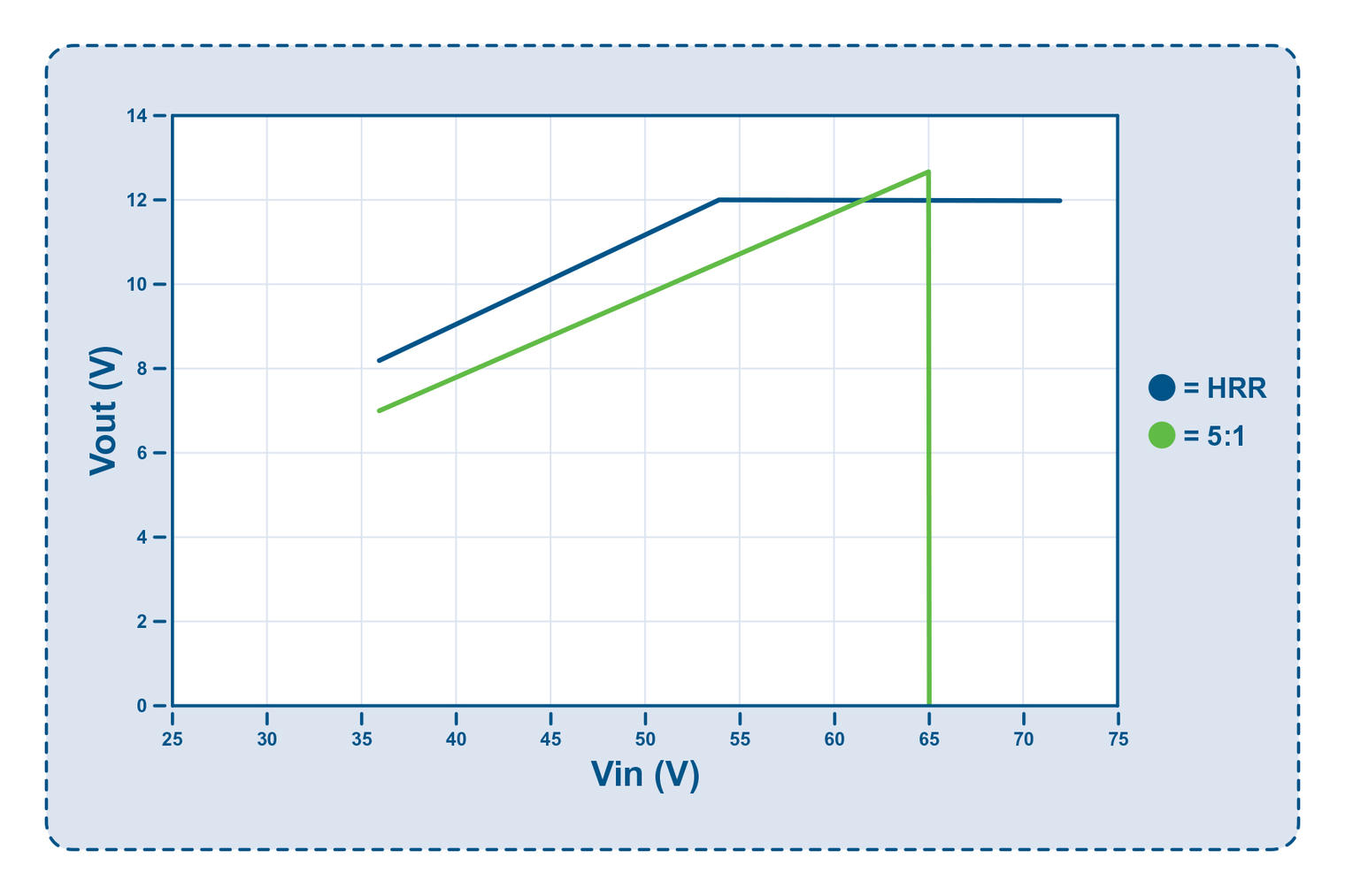
Figure 1: HRR operation is similar to fixed ratio at lower Vin but limits Vout at higher values of Vin
Examining HRR operation under various conditions can reveal how the converters are used to best advantage, quantifying the benefits in terms of efficiency and system design.
HRR and fully regulated converter comparison
Figure 2 and Figure 3 illustrate the HRR converter’s power capability and efficiency. Figure 2 shows that for fixed maximum output current, HRR can be designed for the highest power at the nominal Vin of 54V with some derating at high voltages due to switching losses reducing efficiency.
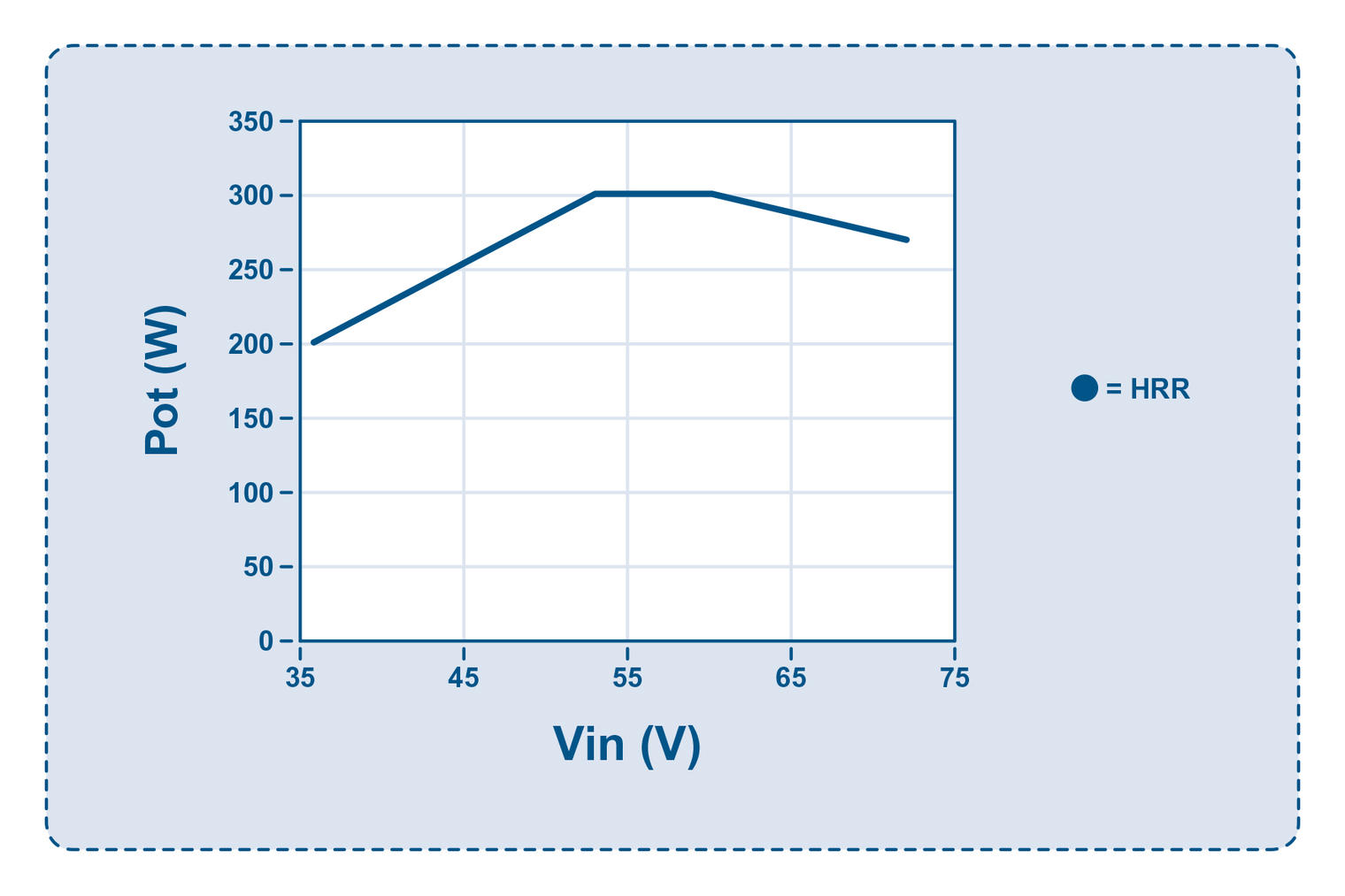
Figure 2: HRR converter maximum output power occurs when Vin is close to the nominal value of 54V
The efficiency curves in Figure 3 show that a HRR converter is also increasingly efficient as Vin rises to the nominal 54V, because of reducing resistive and other voltage drops, as the current reduces with increasing output voltage, at constant load power. This is especially true at high load. Note that although the efficiency and maximum output power are both reduced at the lower values of Vin, the performance remains impressive. Efficiency of 95.1% when delivering 200W from 40Vin is good performance for an intermediate bus converter.
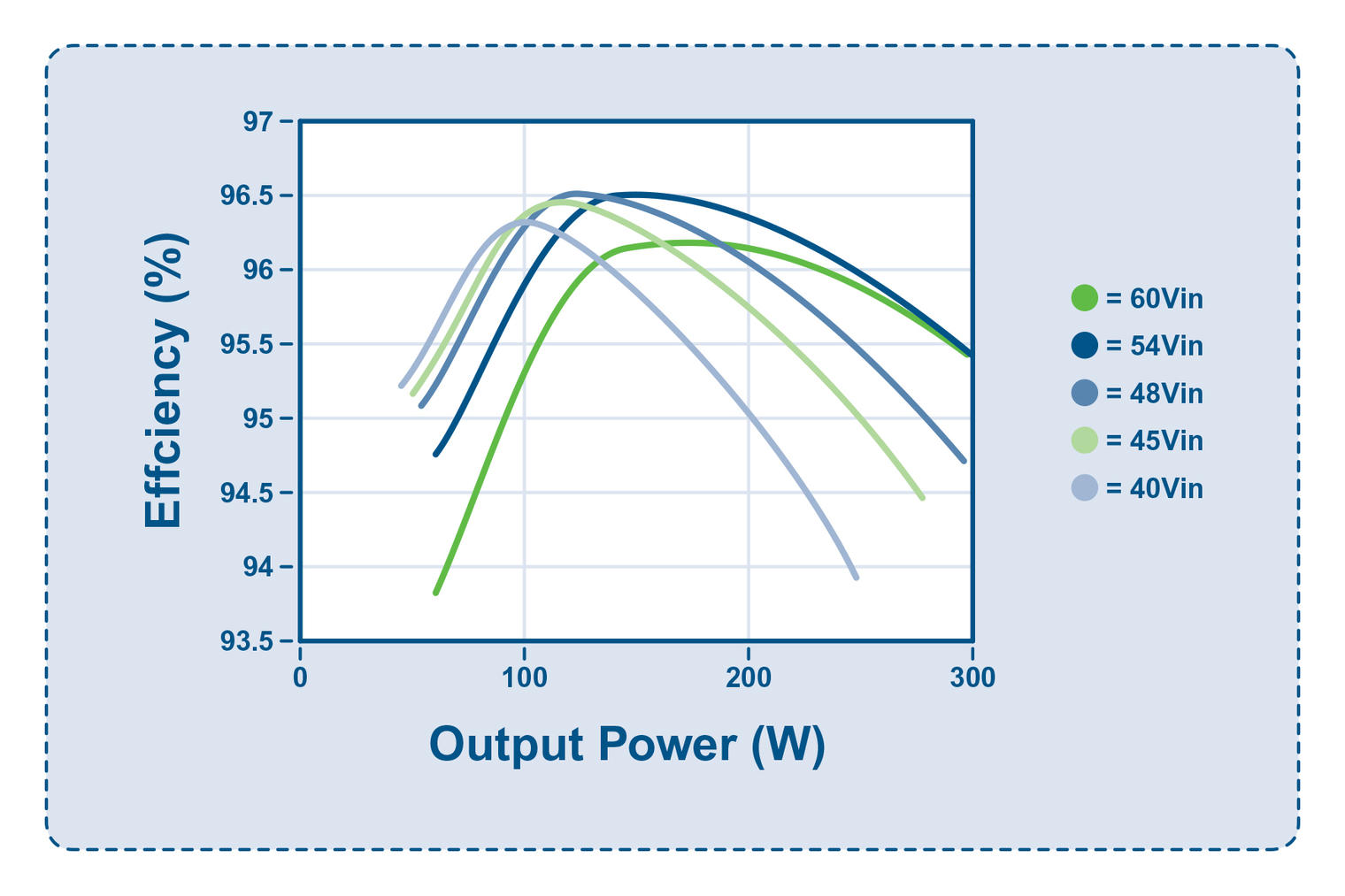
Figure 3: HRR converter efficiency peaks at nominal input voltage
Comparing the performance curves across the range of Vin values with those for a fully regulated fixed-output 12V converter, in this case a Flex Power Modules PKU4213D, highlights a key advantage of the HRR converter: Figure 4 shows the set of efficiency curves for the Flex Power Modules PKU4213D, indicating that the best performance is at low Vin where duty cycle is higher. However, intermediate bus converters rarely operate with such low values. In practice, Vin is typically around the nominal value most of the time, and this is where the HRR converter achieves best power capability and efficiency. This delivers major advantages over the fully regulated converter for end users, including lower utility bills, lower operating temperatures, reduced demand for cooling, better reliability and longer equipment operating lifetime.
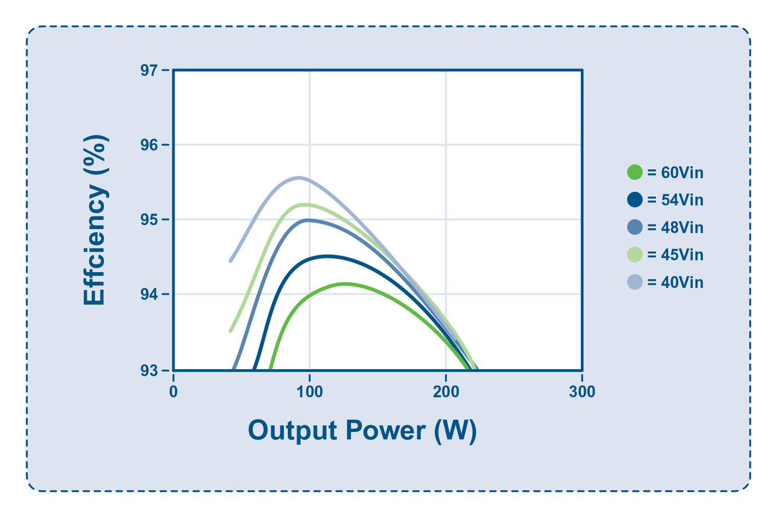
Figure 4: Efficiency of a fully regulated IBC is typically best at low input voltages
Note that even at lower values of Vin, HRR outperforms the conventional technology. Efficiency is 1.2% higher at 150W and 40V input. At 200W and 54V input, this improvement increases to 2.2%.
Fixed-ratio converter comparison
High efficiency is the main attraction of using a fixed-ratio converter with duty cycle always near 100%, but this only applies for a limited range of input voltages. However, the HRR technique compares very favorably and, in some cases, can be superior.
Covering an input range up to 60V will likely require a 5:1 fixed-ratio converter. In this case Vout will be approximately 10.4V at 54V input, which provides a good combination of efficiency and dynamic performance. A comparable 4:1 HRR converter could be selected with a limiting Vout of 12V or 10.4V (for example the PKU4217D). The 12V option transitions to ratio mode at around 50V, delivering very similar performance to the fixed-ratio type when the input is nominal at 54V. The 10.4V option transitions at about 43V, giving a slight performance penalty for the converter at 54V where the duty cycle has decreased significantly. However, the lower voltage to following PoLs is likely to make them more efficient, so the overall effect may be minimal.
If Vin dips, however, so does the performance of the fixed-ratio converter. At 40V input, a 5:1 fixed ratio converter produces about 7.7V output. This forces the converter to operate with 35% higher output current than at nominal Vin/Vout for the same load power. The HRR module reduces to only about 9V so the current increase for fixed-load power is less, yielding a significant saving in resistive distribution losses.
In this scenario, while the 10.4V HRR converter might have a small disadvantage in maximum power at nominal Vin, it has a flatter Vout profile across the input voltage range and a more consistent output power curve. Put simply, this means that it can deliver more power under conditions where it is most needed.
Handling input transients
While the HRR technique has been shown to deliver valuable gains in efficiency and power under the most common operating conditions, its response to steep positive-going input voltage transients can be made superior to fixed-ratio converters, making them particularly attractive in the telecom industry.
Figure 5 compares the responses of three different DC-DC converters to a steep input transient from 48V to 54V.
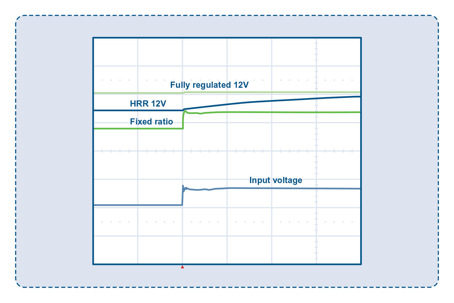
Figure 5: Fully regulated, fixed-ratio and HRR converter responses to a 48V to 54V Vin transient
The upper trace shows the response of a PKU4213D 17A converter with fully regulated fixed-output voltage of 12V powering an 8.5A load. There is minimal change in Vout, as would be expected.
The second trace is from a 12V, 25A HRR converter with a 12.5A load. The smoothly ramping Vout takes approximately 4 milliseconds to adapt between output voltages, in this case transitioning between “ratio” mode and constant output voltage mode.
The lower trace, for a 9.6V 42A fixed-ratio 5:1 converter with 12.5A load, shows Vout following Vin with a step-change in voltage.
A following PoL converter may pass the step-change in input voltage from a ratio converter to the PoL load as a transient, causing functional problems or even damage. The HRR technique with its active control can momentarily reduce the duty cycle and slow the IBC output voltage change before reverting to 100%, thus protecting the PoL.
The step voltage that can be passed by a fixed-ratio converter also causes high transient current into the IBC output capacitors. Figure 6 shows example current in two 470µF output capacitors during the Vin transient from 48V to 54V for the 5:1 fixed ratio converter considered before.
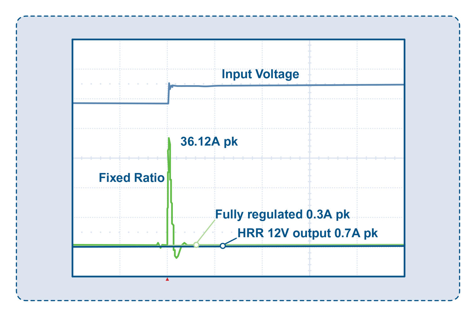
Figure 6: Output capacitor current response to a Vin transient for fixed-ratio, fully regulated and HRR converters
For the fixed-ratio converter, the charge current to the capacitors reaches 36.1A due to the very sharp Vout change. The converter is overloaded (12.5A + 36.1A > 42A) and output droops significantly. Doing the same test with a step from 40V to 54V causes the converter to enter overcurrent protection.
With the HRR converter, the capacitor charging current is just 0.7A, which compares well with the charge current of 0.3A for the fully regulated fixed-output converter. This is one of the important benefits of HRR. The PKU-D HRR products from Flex Power Modules actually have a constant current characteristic on overload, with shutdown and restart if the overload persists.
Negative transients can be troublesome in ratio converters
Most modern converters use the output synchronous rectification (SR) technique to replace discrete diodes for best efficiency. The technique does have a disadvantage, though; the MOSFETs configured as rectifiers can sink as well as source current. If a fixed-ratio converter experiences a negative-going input transient, the output immediately tries to drop, and because the 100% duty cycle switching is maintained, current can flow backward from the charged output capacitors, reflecting to a high reverse current on the input. This can also affect a HRR converter, but a feature of the Flex Power Modules HRR parts is reverse current detection that, in the worst case, sends the converter into standby mode until the output voltage falls to the correct level. The load is unaffected as the output is still, by definition, held up by the output capacitor in this situation.
Input ripple rejection is better with HRR
For fixed-ratio converters, any low-frequency ripple voltage on the input is passed straight through to the output in proportion to the ratio, with even the possibility of amplification due to “peaking” in input and output filters at higher frequencies. With the HRR technique, ripple is similarly attenuated by the conversion ratio at low frequencies but, because the duty cycle is never quite 100%, some “feed-forward” PWM can be applied to attenuate ripple. Figure 7 shows the resulting ripple attenuation of a HRR converter with the expected 4:1 attenuation up to 1kHz increasing to around -35dB at 10kHz.
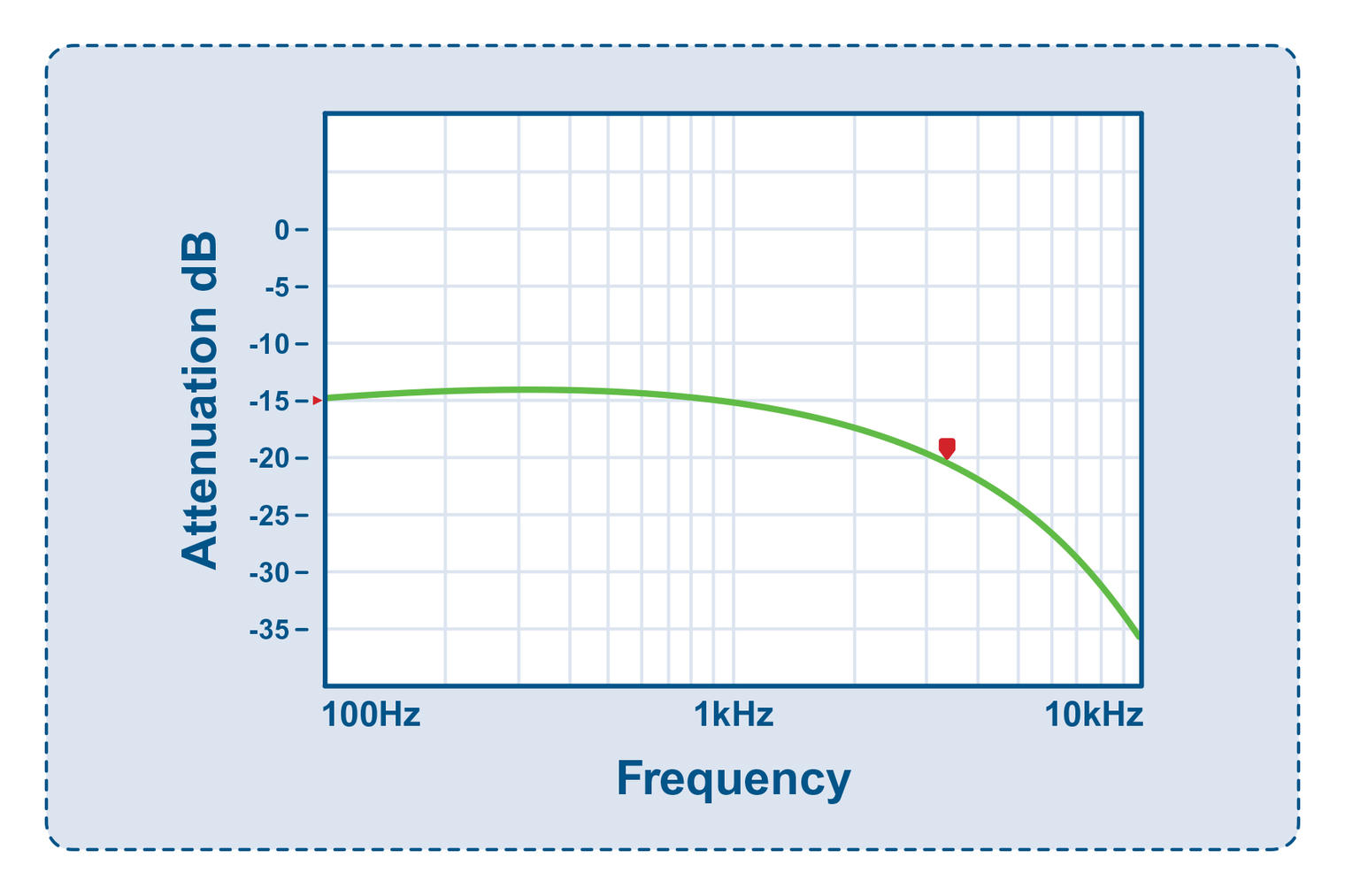
Figure 7: HRR converter – input ripple voltage attenuation
Compare this with the attenuation plot from a fixed-ratio converter in Figure 8 with the 5:1 (-14dB) attenuation up to 1kHz but just -10dB at 10kHz.
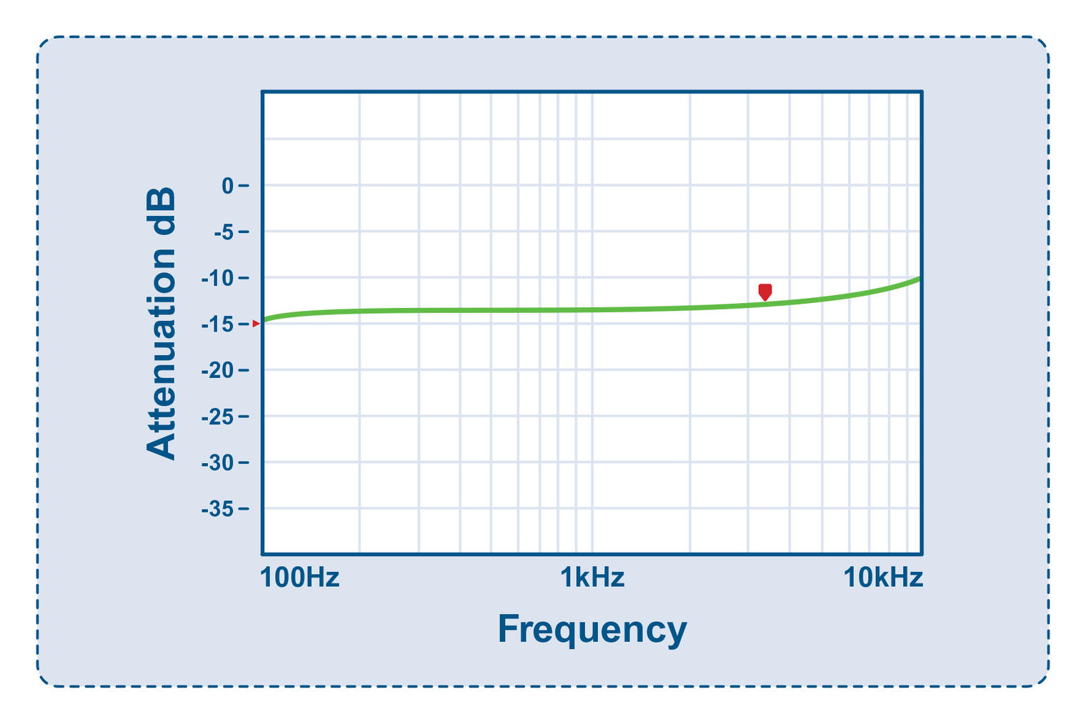
Figure 8: Fixed ratio converter – input ripple voltage attenuation
The peaking at higher frequencies up to 100kHz due to input and output filter resonance in an example fixed-ratio converter is shown in Figure 9, resulting in 350mV output ripple for 200mV input (+5dB) at around 20kHz.
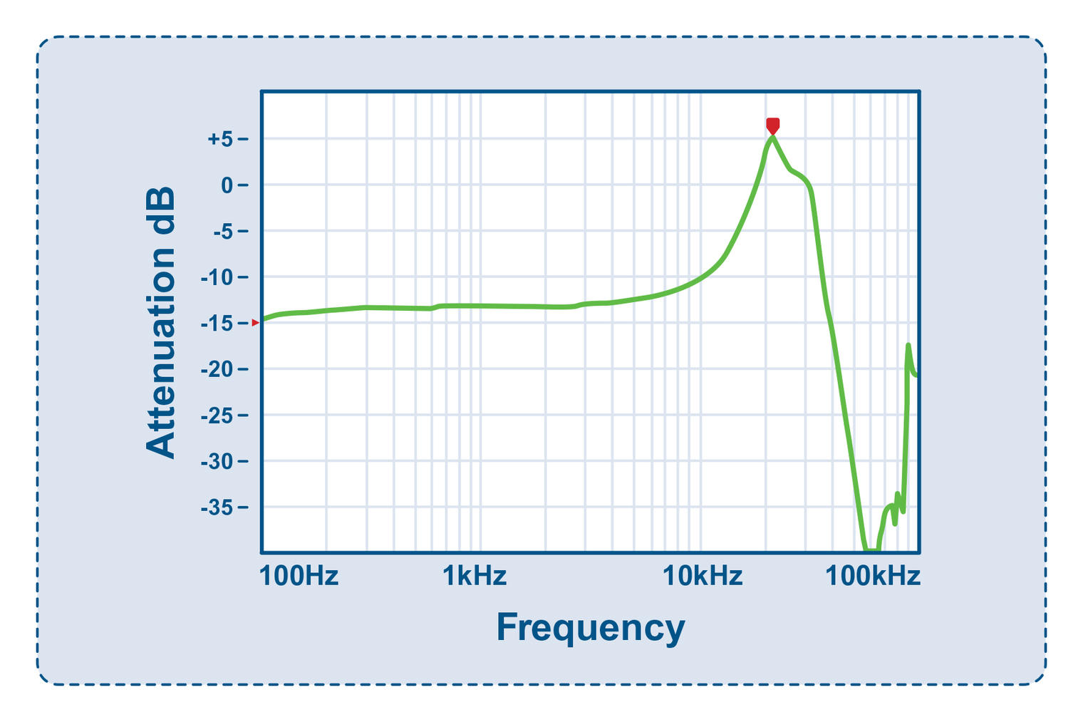
Figure 9: Input and output filters can produce amplification of input ripple voltage
Conclusion
Neither a fixed-ratio nor a fully regulated fixed-output converter can provide an entirely satisfactory way of generating an isolated intermediate bus to power non-isolated PoL converters. A fixed-ratio converter, although efficient under certain circumstances, cannot handle the full range of input-voltage variation required by ETSI standards and does not handle input transients well. A fixed-output converter is relatively inefficient around the nominal input voltage.
The Flex Power Modules proprietary hybrid regulated ratio technique enables greater efficiency and power delivery under the most common operating conditions, permits a wide input voltage range, and provides superior response to transients with low output ripple. These advantages ensure strong performance in telecom, industrial, laboratory and other applications where distributed power architectures with isolated IBCs are used. Converters from Flex Power Modules incorporating HRR technology are available in power ratings from 260W to 1300W, with significant energy savings accrued from their use delivering a rapid return on investment.
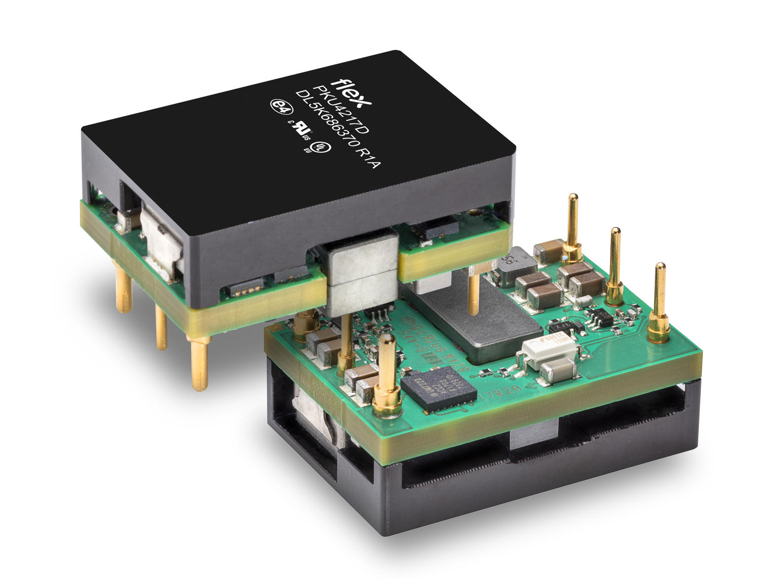
Figure 10: Flex Power Modules PKU4217D
