Peak power ratings of our DC/DC converters
Introduction
There’s an old engineering rule about how tight to make a screw fixing – wind it up until the thread just strips, then back off a quarter turn. Joking apart, every engineer in mechanical or electrical design works with a margin between what they know is an acceptable working stress and what will cause something to break. When that stress is the loading of a DC/DC converter, the time duration also plays a part – microseconds overload is surely OK but when it lasts longer - milliseconds, seconds, at what point does damage occur?
Some designs of DC/DCs can accurately measure and limit output current to a value that is safe under all conditions. but they are not allowing the potential advantage of delivering the short peak loads that modern processors and complex ICs often demand. If they can be rated for a ‘peak’ loading then DC/DCs can be physically sized for a lower continuous power, making them smaller and cheaper. We put names to the levels of loading for our DC/DCs that have a peak power rating: ‘Continuous’, ‘Peak Power’ (PP) typically lasting less than one second and ‘Transient Peak Power’ (TPP) for much less than 100ms (Figure 1).
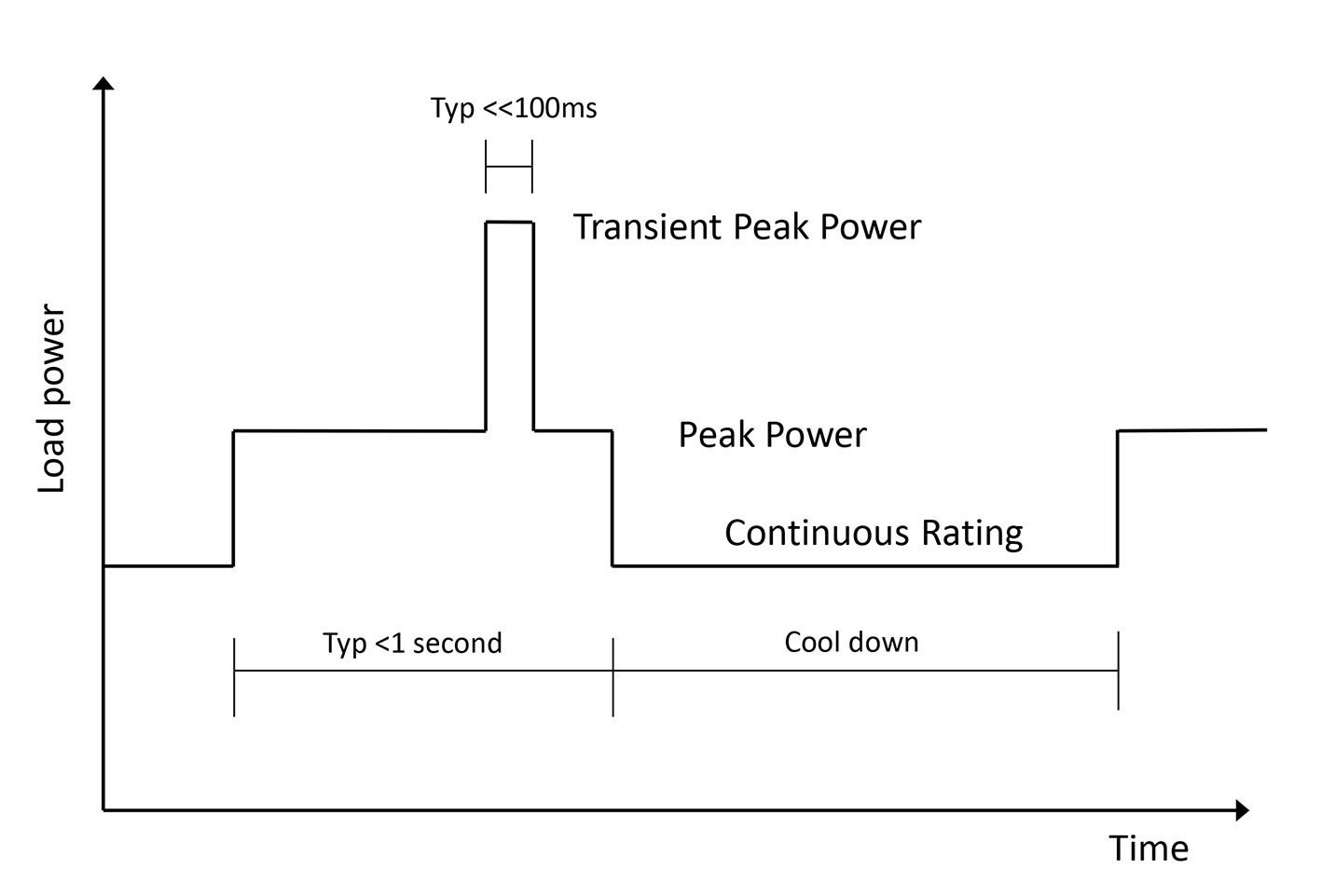
Figure 1: Load power ratings defined for our DC/DC converters
What limits peak power capability
There can be different limiting factors with peak power demand – if there are magnetic elements in the power path such as an output filter, then saturation can occur and although this doesn’t harm the choke directly, it loses inductance and can cause a damaging peak current in diodes and switches. This is an almost instantaneous effect, so DC/DCs with PWM that need a choke might have limited peak load ratings. An example would be the fully-regulated BMR350 with an allowed peak power ‘only’ 30% higher than the continuous rating. Other DC/DCs that run at 100% duty cycle such as our BMR313 have no output choke and do not suffer from the limitation, resulting in a peak rating of 3 kW, 3x its continuous rating of 1 kW.
In the case of the BMR313, the limit is now semiconductor junction temperature rise and the challenge is to quantify the combinations of starting temperature, peak current and duration that are within a ‘safe operating area’.
Quantifying the overload
If junction temperature is now the limit, a way has to be determined to measure it, so it will not exceed an ‘absolute maximum’. The semiconductor device manufacturer will typically set 150°C or 175°C as the limit – often simply because it is unqualified beyond that point and survival can’t be guaranteed. You could guess that they have added their own safety margin but this can’t be assumed. A direct measurement of temperature would be ideal, but a sensor can only get so close, so junction temperature has to be extrapolated. This means modelling the thermal resistances and capacitances around the junction and knowing what power is being dissipated. With limited ‘peak power’ events, the temperature changes along the heat path from junction to ambient are relatively slow and predictable. If an accurate thermal model is assembled, a thermal sensor coupled with power loss and time measurements can now generate a warning signal before a critical temperature level is reached and this can be used to signal to the load to ‘throttle back’, if it has the capability. Otherwise, a second threshold is crossed, and the DC/DC is instructed to shut down. However, with high level ‘Transient Peak’ overloads, rates of temperature rise are higher and are dominated by the local thermal capacity of the semiconductor die itself, with the effects more difficult to characterize. In this case, a prediction of junction temperature can be made by measuring starting temperature, transient load current and its duration. This is the technique used in the BMR313 which includes multiple thresholds and warnings for timed over-current with a fast hardware shutdown for extreme levels, a slower timed shutdown for intermediate current levels and a temperature sensor to provide a warning signal and eventual shutdown (Figure 2).
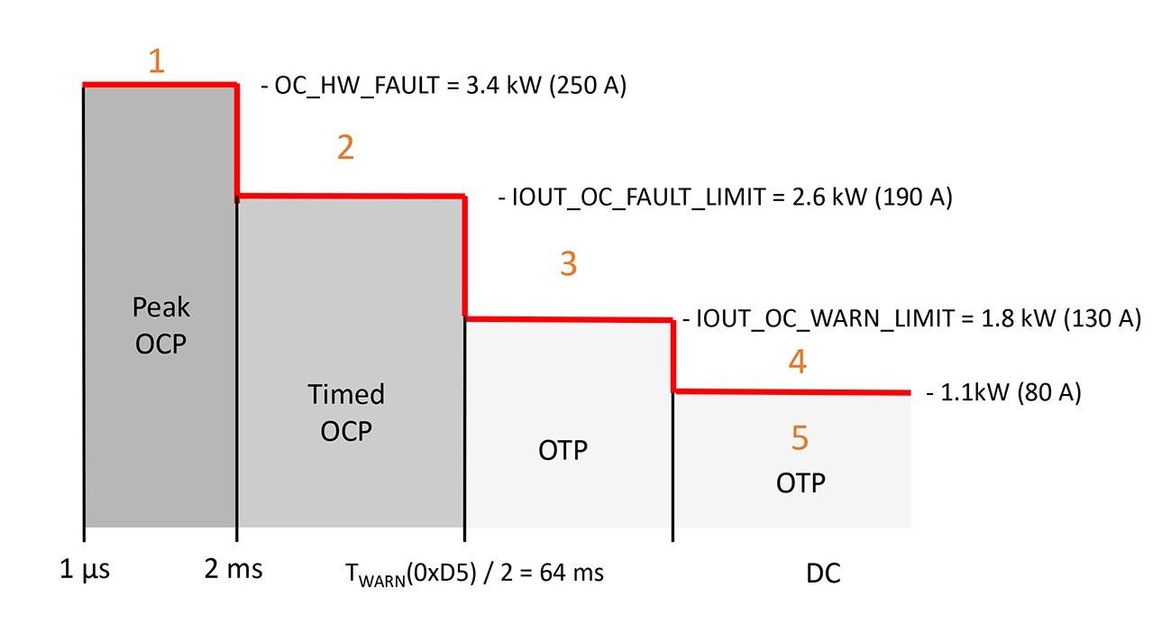
Figure 2: The BMR313 continuous, peak and transient peak power protection scheme
Repetition of peak load complicates matters
The protection scheme used in the BMR313 assumes that the die cools down to equilibrium before the next peak current event, but that may not always reflect reality – peak load repetition rate cannot be predicted. Another approach, adopted in the BMR350, is to monitor load and timing, but filter its resulting analog of junction temperature with a proportion of the previous measurement, the so-called ‘Exponential Moving Average’ (EMA) method. This then allows for the varying cool-down periods and their durations providing robust protection for the part, particularly as it is regulated, constraining its peak power capability. The EMA method can be extended with multiple averages representing different elements of the heat path, for example to include modelling of the die on its own, with its fast thermal response.
The techniques described and implemented in our DC/DC converters allow peak loads to be handled without having to oversize the converters, but with confidence that they are not being over stressed. More details of the methods used can be found in the white paper ‘Peak Power Load Management in DC/DC Converters’ available to download HERE