Thermal paths and the impact of “open-deck” baseplates in DC/DC converters
Introduction
Thermal management has become a critical topic in modern electronics. Large-scale server farms and power systems increasingly highlight their cooling capabilities-and for good reasons. Efficient heat dissipation directly impacts performance, reliability, and efficiency.
When it comes to DC/DC converters, understanding thermal flow is essential. This blog explores how thermal systems work, why bottlenecks occur, and how design choices such as “open-deck” baseplates that don’t cover the entire surface area of the DC/DC converter affect overall thermal performance.

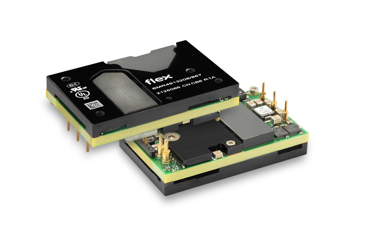
Figure 1: BMR491 with "open deck" baseplate
1. The fundamentals of thermal flow
Every component in a thermal system can be classified as one or a mix of:
- Heat Source – Components generating heat (e.g., transistors, transformers).
- Heat Dissipator – Surfaces or structures that release heat into air or liquid.
- Heat Conductor – Materials that transport heat between sources and dissipators.
Heat Sources
In DC/DC converters, heat sources include components carrying electrical current or magnetic fields. Losses in these materials create heat.
Heat Dissipators
Heatsinks and airflow systems dissipate heat to the air. Their efficiency depends on surface area, design, and airflow. Thermal resistance measures how much temperature rises for a given power loss.
Heat Conductors
Metals like copper, but also even ceramics, are excellent thermal conductors. Copper is particularly interesting because it conducts both electricity and heat. However, when copper traces carry current, they also generate heat, turning a conductor into a source. This dynamic nature explains why thermal resistance is not a fixed value.
2. Thermal mass and time constants
Materials have thermal mass – the energy required to change their temperature. Air has a low thermal mass, while water has a high thermal mass. This affects transient thermal behavior due to differing thermal time constants within the system:
- FET die: 10-50 ms
- DC/DC converter: 2-10 s
- Complete system: minutes
This means that field effect transistors (FETs) react quickly to load changes and rapidly change temperature, while the larger system responds more slowly.
3. Designing for thermal efficiency
The goal is simple: minimize thermal resistance near heat sources and progressively spread heat to larger areas.
Example:
- A FET with a 2×2 mm thermal pad dissipating 1 W → 250 mW/mm².
- Heat flows to a baseplate and then a heatsink.
- Even with an open-deck baseplate (35% open), thermal flow drops to 25 mW/mm².
Surprisingly, covering the entire baseplate doesn’t always improve performance, as the bottleneck is usually near the transistors.
4. Heat spreading and heatsinks
Heat spreaders distribute heat in the X-Y plane and increase contact area with heatsinks. However, as heat flow rises, spreading becomes harder – requiring thicker spreaders.
Heatsink Design
- The base of the heatsink helps move heat, adding to the dc/dc baseplate.
- The orientation of the fins matters when it comes to heat-spreading.
- Surface area and orientation play a large role for performance.
- Copper heatsinks perform best in managing uneven heat distribution.
Thermal blocks (liquid)
Thermal blocks excel at removing heat from small contact areas, reducing temperature gradients. But these higher cooling capacities often lead to higher power requirements, creating new challenges.
5. Open-deck baseplates: pros and cons
Open-deck designs leave gaps for the tall magnetic materials like ferrite, which have high thermal resistance and low self-heating. Covering these gaps with thin aluminum only helps when the cooling solution cannot bridge the gap.
Integrated heatsink-baseplate designs have been tested and work technically – but commercial adoption remains limited.
6. Thermal modeling
Thermal analysis is complex, involving multiple sources and conductors. There are typically two approaches:
- Empirical Testing – Measure thermal resistance in controlled environments.
- Simulation – Model during design phase, refine with real-world data.
Modern simulations are increasingly accurate thanks to iterative feedback loops.
7. Thermal revolution
The term might sound bold, but the evolution in thermal design has been nothing short of revolutionary. Looking at Flex Power Modules’ digital quarter-brick converters over the years, output power has increased dramatically – from 400 W to 2 kW continuous power.
What enabled this leap? While improved components and topologies play a role, a significant part of the progress comes from better thermal properties.
For example:
- Comparing early BMR453 modules to the latest BMR491 and BMR352, thermal resistance from hotspot to baseplate has dropped by 3-4 times.
- In practical terms, where the BMR453 could dissipate 25 W to a cold wall, newer products can handle 75-100 W under similar conditions.
This improvement means that once heat reaches the heatsink, airflow speed, heatsink size, or even liquid cooling become necessary considerations to unlock full performance potential.