Top & bottom cooling options for integrated power stages
Introduction
Latest server applications such as AI and machine learning are very power hungry, and at the same time data center managers want to cram more blades into a rack to improve utilization of the space available. This puts strains on the power delivery network, particularly the ‘Point of Load‘ DC/DC converters or ‘Voltage Regulator Modules’ (VRMs) that see high currents in the tightest of spaces. In response, VRMs have been developed to be highly efficient and closely integrated with the end load, and one approach is to make the VRM power stage a separate module, with its user-chosen controller placed elsewhere. These ‘integrated power stages’ use space very efficiently and achieve staggering power density, around 150 W/cm3 or higher from packages with a footprint of less than 1 cm square. However, even though efficiencies of well over 90% are achieved, that does still mean 10 W or so of power to be dissipated and led away from the module.
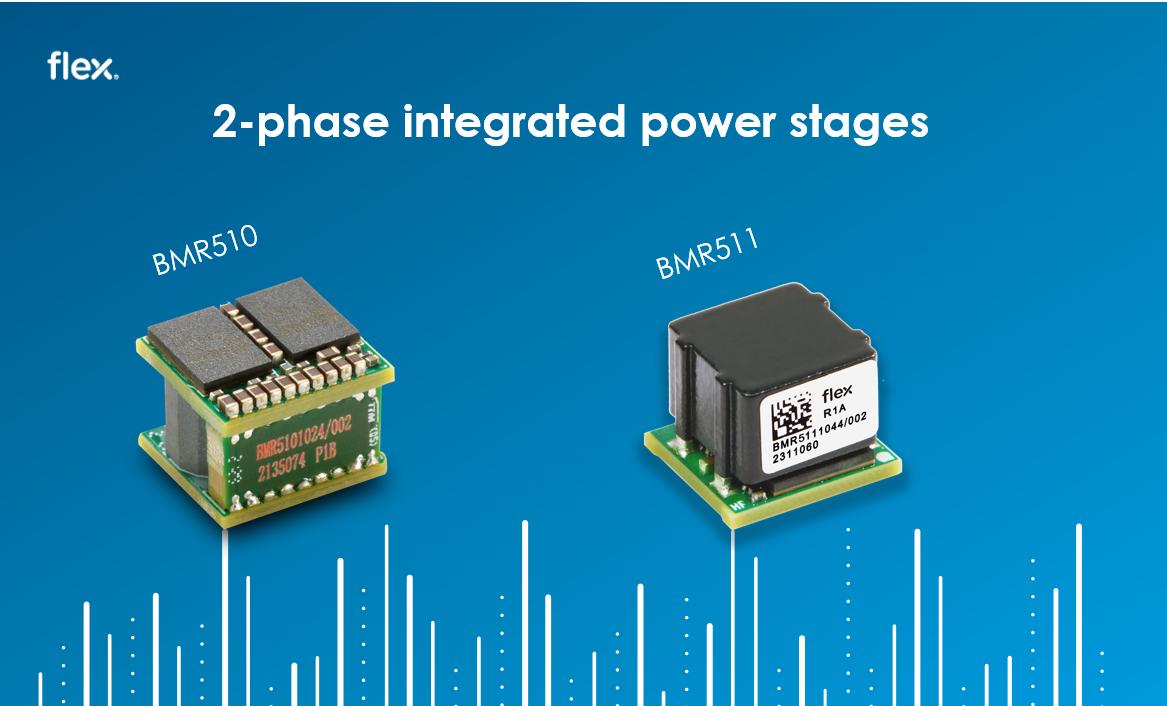
The Flex Power Modules BMR510 and BMR511 intelligent power blocks are great examples of the state-of-the-art, with continuous current ratings of 80 A (160 A peak), a wide input range up to 15 V and a settable output down to 0.5 V. The BMR510 and BMR511 (Figure 1 left and right respectively) are distinguished by different approaches to the cooling issue: the BMR510 is top-side cooled and the BMR511 is bottom-side cooled. Both are available with LGA or, optionally, solder-bump terminations.
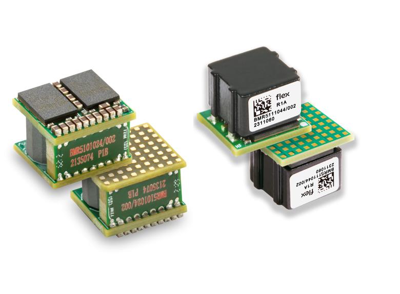
Figure 1: The Flex Power Modules BMR510 (left) and BMR511 (right) intelligent power blocks with top- and bottom-side cooling respectively
The cooling alternatives
The BMR510 is arranged so that the main heat-generating semiconductors are on a top-side daughterboard with semiconductor surfaces that are coplanar, and that a cold plate or heatsink can be simply attached, typically clamped on with a thermal gap-pad. Some small proportion of heat dissipation is provided by conduction through the module and its terminations to the host board and some by convection to the surrounding air. To take this into account, Flex Power Modules provides a derating graph (Figure 2) that includes cold-plate temperature and host board temperature, showing that the full 80 A may be drawn with 13.5 V input up to 90°C cold plate/60°C board temperature. This is with an insulating 0.5 mm gap-pad, thermal conductivity 3.5 W/m.K. The top-cooling approach suits applications where there is some space above the host board for a cold plate or heatsink with forced or convection cooling air, or if the host board has limited capability to dissipate heat through its bulk and copper planes.
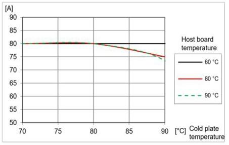
Figure 2: The top-cooled BMR510 intelligent power block derating with cold-plate and host-board temperature
The BMR511, in contrast, is designed for bottom-side cooling with heat from the semiconductors mostly passing through the module substrate and through the terminations to the host board. The top side of the module is the flat surface of the main inductor and this is also available for attachment of a heat sink or cold wall for additional cooling. As the thermal resistance to the host board is relatively high, the BMR511 is commonly specified with some airflow and can achieve its full 80 A output to over 80°C ambient at 4 m/s flow rate, Figure 3. If a cold plate is used, the full 80 A output can be obtained at 12 V input up to 90°C host board and cold-plate temperature. This is with a 1 mm gap pad, thermal conductivity 8 W/m.K. The application for the BMR511 bottom-cooled approach is when there is little or no space above the module, forced air is available and when the host board is designed to dissipate power through its surfaces.
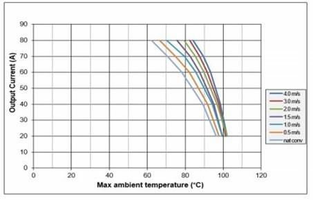
Figure 3: The bottom-cooled BMR511 intelligent power block derating with ambient temperature and specified airflow
Verifying the performance
All applications are different in their mechanical arrangement, airflow and thermal resistances to their ultimate sink for thermal energy, so Flex Power Modules defines their module thermal performance comprehensively. This means tests with defined module orientation, airflow rate and temperature, along with defined host board and cold plate dimensions and their thermal resistances. In the product data sheets, critical points are identified with their maximum allowed temperatures. Over-temperature protection is nonetheless included, and temperature can be reported for remote monitoring. As an additional aid, thermal models for both products are available from Flex Power Modules on request.
Conclusion
Space above a host board determines whether top-cooling with a heatsink or cold-plate is viable and if so, concerns about the host board’s ability to dissipate heat are not so much of an issue. If bottom-cooling is chosen, for space reasons or to save cost of heat sinking and its fixings, the host board must be designed and evaluated for its heat dissipation ability, and controlled airflow will normally be necessary. In either case, integrated power stages from Flex Power Modules perform well with their full rated output available.