AI - the need for higher power density with maximum efficiency

Article
One definition of ‘Artificial Intelligence’ is software that mimics and generates human-like behaviors. Whether this is desirable is a subject of debate and there will be many who would prefer guaranteed rational and deterministic responses from the machines and automated services that surround us. However, AI is here to stay and, supported by the cloud, it represents a business that is worth around $136B in 2022, projected to rise to nearly $2T by 2030, according to Grand View Research [1]. One worthy function of AI is the minimization of energy consumption both in the home and in industry, but AI computing itself consumes huge amounts of power, both in the ‘learning’ phase and in routine use. The largest data centers require a feed of more than 100MW as a result and this represents a high cost in dollars and to the environment, through the resulting carbon footprint. We’re considering AI, but of course other increased burdens include crypto currency mining, the IoT and social media/streaming.
A success story has been the relatively slow growth of energy consumption of data centers compared with ballooning data throughput and this has been largely due to continued improvements in energy efficiency of hardware and their power supplies. However, rack power density requirements are said to be 3x higher for AI than traditional data center functions and further efficiency gains get progressively more difficult to achieve. As a result, system designers are continually revisiting their power delivery architecture to look for ways to improve efficiency in the process of converting utility AC down to the sub-1V DC levels often required for GPUs, CPUs, FPGAs and ASICs.
The evolution of rack power architecture
There are many considerations when designing a power distribution architecture in a data center. These include voltage and current levels for safety and loss considerations in distribution and conversion, the need for functional and/or safety isolation, the physical size of power conversion stages, cooling arrangements, where and if tight voltage regulation is needed and of course, cost. All these factors have changed in emphasis over the years and as power levels have increased, the optimum arrangement also changes. When loads were relatively low and end-voltages were 12V or 5V with perhaps -12V for analog and interface circuits, it was practical to have an AC/DC converter for each rack shelf with multiple DC outputs, Figure 1, (left). Wiring for this arrangement is bulky and expensive with the necessary safety isolation, back-up can only be via a preceding UPS and duplicating the AC/DC function in every shelf is also costly. A logical progression as loads increased was to have a bulk AC/DC converter for a cabinet, perhaps with redundancy, and then to route DC via bus-bars around to each shelf, Figure 1, (right). This was initially at 12V but 48VDC became common to keep current low and ohmic losses 16x less, but still at a ‘safe’ voltage, also allowing easier integration of 48V batteries as backup. Each blade then needed to down-convert 48V to the end voltage and this was most often done with an isolated, regulated intermediate bus converter to 12V, then down to the chip level voltages with non-isolated, fixed-input ‘Point-of-Load’ (PoL) converters.
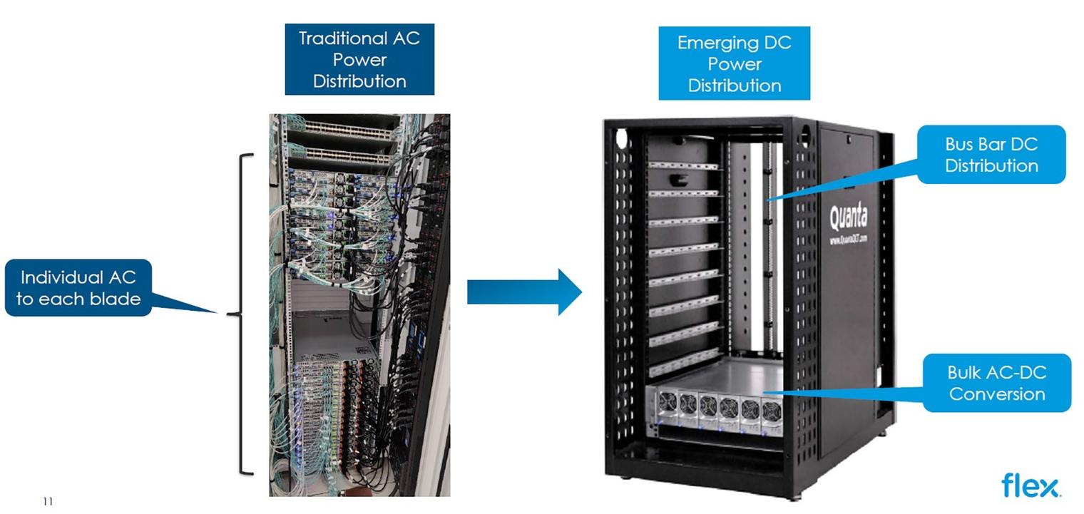
Figure 1: Datacenter rack power architecture evolution
‘Current’ practice
As power levels have inexorably increased, with 30kW per rack now common for AI applications [2], power density of conversion becomes more of an issue, so there is an increased emphasis not only on efficiency but also on the ‘watts/in3’ specification for DC/DCs, along with the conflicting demand of ease of heatsinking. This has led to the approach of using an intermediate bus converter DC/DC with a fixed conversion ratio and without isolation, which yields the highest efficiency, smallest size and lowest cost for a given power output. Without isolation, common ground paths have to be managed but this is not a major concern with a limited power distribution range. The following PoL converters must now have a wider input range, as their supply varies in a fixed ratio to the 48V bus and the ratio of the bus converter can be chosen from typical values of 4:1 (48V to 12V), 6:1 (48V to 8V), or 8:1 (48V to 6V) to suit the peak efficiency ‘sweet spot’ of the PoL converter. Lower conversion ratios and higher PoL supply voltages result in lower bus currents and lower losses in PCB connections while PoLs are often more efficient with a lower input voltage from higher bus converter ratios. A further option, pioneered by Flex Power Modules [3], is their ‘Hybrid Regulated Ratio (HRR) scheme [4], where the bus converter is unregulated up to a certain input voltage, above which the output is regulated. This reduces the overall input voltage variation to following PoLs allowing more efficient types to be utilized. 48V over-voltage transients are also prevented from passing through the converter, improving reliability and reducing peak voltage rating requirements of the PoLs.
System considerations are important
Headline goals in a rack power architecture are high conversion efficiency and power density, but a ‘holistic’ view should also be taken: active cooling, for example, is a major cost, consuming power itself and if the main system dissipation is in converters on blades, the route for heat extraction has to be considered. Low profile bus converters optimized for top-side cooling are advantageous in this respect, allowing heat extraction through attached cold-plates or heatsinks with blown air or even liquid cooling.
Losses in interconnections can be substantial at higher power and initial distribution via bus-bars at 48V is a good compromise between safety, power dissipation and ease of coupling-in battery backup. Close to the end IC loads, currents can be at their highest, often 100A-plus, potentially producing high dissipated power in PCB tracking. Voltage is also dropped if the PoL really isn’t directly at the load so schemes that split the PoL converter power and control stages into separate hardware can be a useful approach. For example, a PWM control IC could be fitted directly under a power-hungry device, sensing and controlling voltage to be very accurate while the power stage might be a module on the top-side of the board, adjacent to the end load.
An optimum architecture design will also include considerations of the continuous, minimum and likely peak loads on power conversion and their durations. Intermediate bus converter and PoLs will have a ‘thermal’ rating for power output, limiting long term dissipation and internal temperature rises, but computing loads can have a high ratio between ‘sleep’, operating and peak power consumption. If these values are known and the different power conversion stages have surge current ratings, the converters can be smaller and lower cost than ones rated to supply the peak power continuously. Converters with ‘flat’ efficiency curves down to light loads are also advantageous to leverage the lower system dissipation aims of a load’s sleep or idle modes.
Some example solutions
The Flex Power Modules BMR313 part (Figure 2, left), is an example of a 4:1 ratio, non-isolated and unregulated intermediate bus converter with high peak power capability. It has been developed in co-operation with onsemi and features a continuous power rating of 1kW in an ultra-compact package just 23.4 x 17.8 x 7.65mm in an industry-standard LGA footprint. Peak power capability is however 3kW for an impressive 15kW/in3 surge rating. Input operating range is 40-60VDC for an output of 10-15VDC and comprehensive monitoring, configuration and control is provided through a PMBusTM interface. Efficiency is 97.2% at 54V input and 40A load.
For lower power systems, the BMR320 (Figure 2, middle) has an 8:1 conversion ratio and again is non-isolated and unregulated. The part is rated at 400W continuous and with its output of 5-7.5VDC for an input of 40-60VDC, it matches the input of PoL converters optimized for highest efficiency with lower input voltages. An example is the BMR510 (Figure 2, right), which is a 2-phase VRM or integrated power stage, capable of 40A per phase, 80A total. The LGA-format part is just 10 x 9mm footprint, 7.6mm high, is optimized for top-side cooling and incorporates drivers, power stages and magnetics. With a suitable controller, it can output a programmable 0.5 to 1.3VDC. The input range of the BMR510 is 4.75-16V so it can be used with bus converters with higher output voltages with some reduction in efficiency.
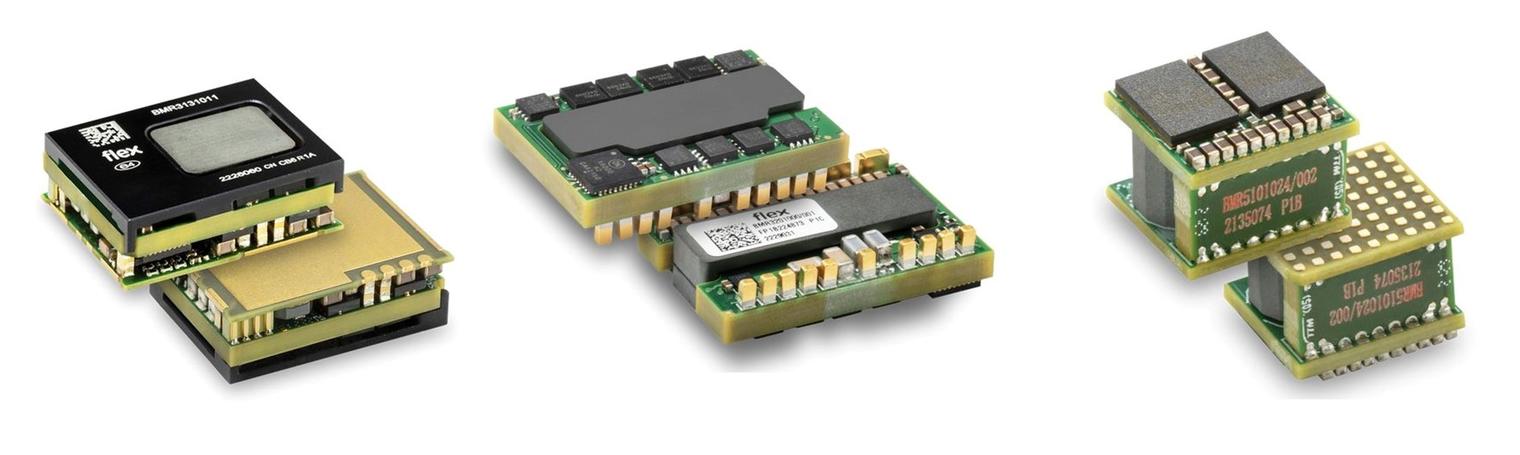
Figure 2: High-efficiency bus converters (left, middle) and PoL power stage (right) from Flex Power Modules
With the options to select bus converter ratio and power rating depending on continuous and peak load demands, there is flexibility to optimize efficiency and where power is dissipated for easiest cooling. Figure 3 shows two scenarios with a BMR313 4:1 bus converter, a BMR320 8:1 bus converter and BMR510 PoL with both scenarios producing the same end-to-end efficiency of about 87% for around 400W total loading. Although the BMR313 is running at well below its continuous rating of 1kW and 3kW peak, peak efficiency occurs at about 400W. The 4:1 solution might be preferable if 12V is anyway required for loads such as PCIe power and dissipates relatively more power in the PoL converter. With the BMR320 at 6V output for 48V input, the BMR510 PoL operates more efficiently, with relatively less power dissipation and relatively more in the bus converter, but this is further away from the end load and perhaps easier to cool. With a 6V bus, the intermediate bus current is higher for the same end load power however, requiring heavier tracking for the same power loss compared with a 12V intermediate bus voltage.
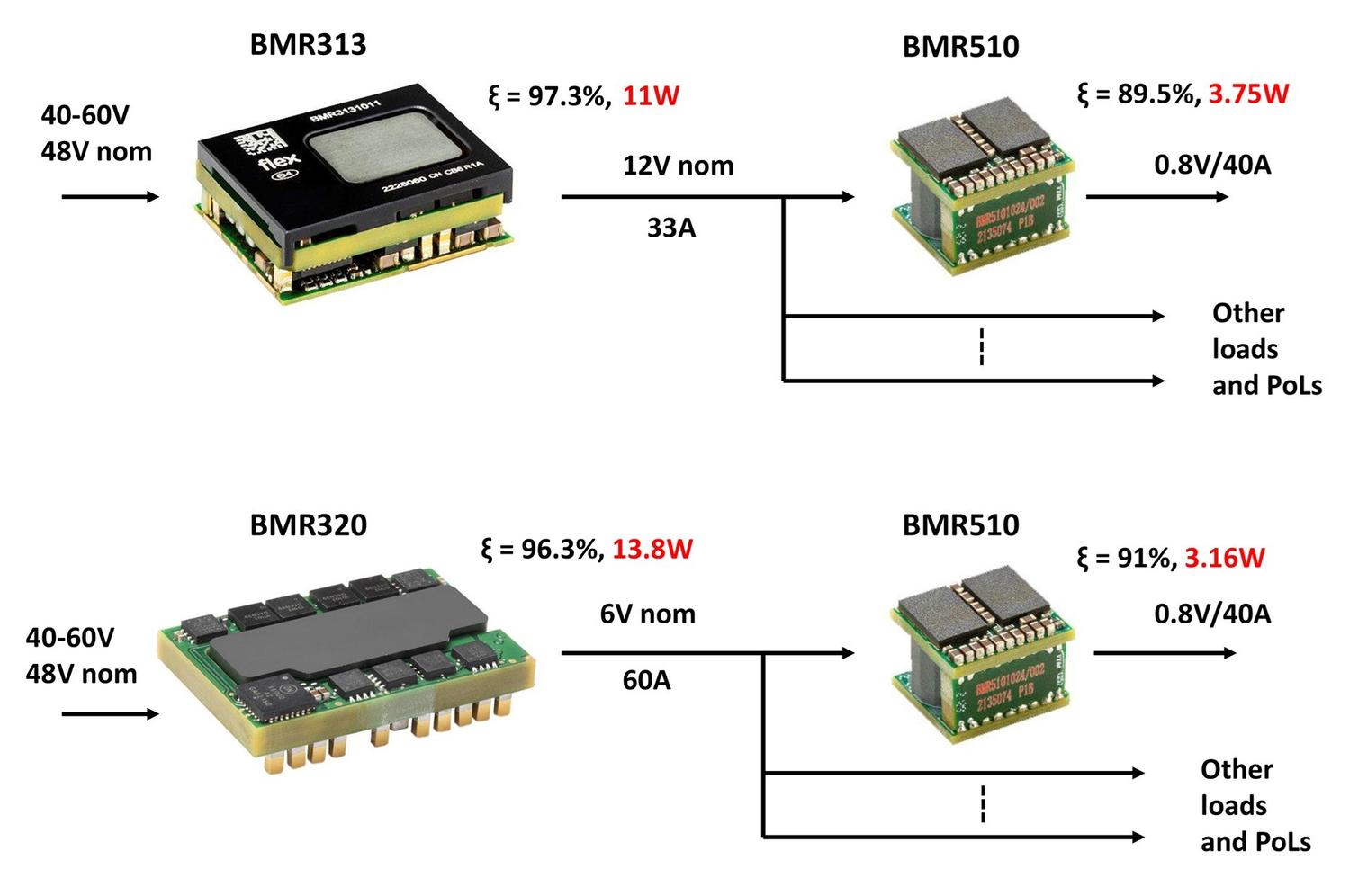
Figure 3: Different arrangements of bus and PoL converters with about the same end-to-end efficiency, but different loss distribution
Conclusion
For a ‘small and mighty’ power architecture, bus and PoL converter data sheets from Flex Power Modules can be examined to find the ‘sweet spot’ of loading, voltage conversion combinations and distribution losses, where efficiency peaks. All parts mentioned are also supported by the Flex Power Designer software [5] for quick configuration and evaluation of performance in a chosen application.
References
[1] https://www.grandviewresearch.com/industry-analysis/artificial-intelligence-ai-market.
[4] The benefits of hybrid regulated ratio topologies for IBCs
[5] Flex Power Designer Software