Isolated vs non-isolated power converters
Isolation - the basics
Isolation in terms of DC/DC converters refers to galvanic isolation which means that there is no metallic / direct conduction path between two parts of the circuit. The isolation will always present a barrier between the input stage and the output stage and may be required for circuit functionality, safety, or both.
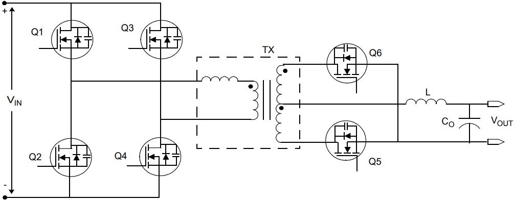
Figure 1: Typical isolated circuit diagram
In an isolated converter, the input and output stage have separate grounds whereas in a non-isolated converter, current is able to flow directly between the two sides as they share a common ground. Isolation is usually created by incorporating a transformer in the circuit so that power is transferred using electromagnetic energy. There is some efficiency loss with this but with a carefully designed transformer, this can be minimised.
In some cases, it is necessary to route signals across the isolation boundary. This is particularly necessary with regulated devices where a feedback signal is required. In order to preserve the isolation, these signals must also be isolated. In the case of AC signals a small signal transformer can be used while for DC signals, the isolation is usually provided by an optocoupler.
Isolation is created by providing electrical insulation between the conductors, either with air or, more often, with some form of tape or other non-conductive material. It is usually expressed as a voltage and applying a voltage above this level can lead the isolation to break down.
Isolated converters – the benefits
Perhaps the biggest advantage of isolation is safety compliance, especially in mains powered equipment. The isolation barrier prevents dangerous mains voltages becoming present on the output where they could come into contact – this is especially relevant in applications such as medical where the patient may be directly connected to the circuit.
There are four primary levels of isolation
- Functional / Operational insulation: this is for operational reasons only, and does not offer any shock protection
- Basic insulation: a single layer of insulation that offers shock protection
- Supplementary insulation: adds another layer to basic to give redundancy
- Reinforced insulation: a single barrier offering double the protection of basic
In many applications, noise can be a problem and as isolated supplies do not share grounds they can be inserted in the circuit to eliminate ground loops. This can be useful to separate a sensitive analog rail from a noisy digital rail.
Non-isolated converters – the benefits
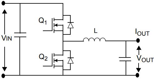
Figure 2: Typical non-isolated circuit diagram
In general, non-isolated converters are less flexible in use than their isolated cousins. However, they do bring a number of benefits for designers where isolation is not required.
The primary difference is that a non-isolated converter does not have a transformer and does not require any physical separation between input and output, so this typically makes them smaller and lighter. It also improves the efficiency as there are no transformer losses to take into consideration.
The design of non-isolated converters tends to be simpler as no isolation is required in any signals crossing the isolation boundary, removing the need for optoisolators and / or signal transformers. This reduction in BOM means that non-isolated converters tend to be lower in cost.
Multi-converter systems
In more complex systems requiring multiple power rails, multiple converters are used to convert a single input voltage to all the voltages the system requires. If isolation is required, then it is not necessary for all converters to be isolated. Often a ‘bulk’ converter is used to step the input voltage down to a lower level before further conversion.
The mid-voltage rail is known as the ‘intermediate bus’ and the bulk converter is often termed an ‘intermediate bus converter’ (IBC) – they are common in telecom systems where they convert the nominal 48/53 V battery voltage to 12 V, before a range of non-isolated converters produce the voltages needed for the various loads. As these converters are placed close to the loads that they feed, these are often called ‘point of load’ converters (PoL).
With a recent trend in high performance applications such as computing, data centers and artificial intelligence (AI) to shift the supply voltage from 12 V to 48 V, primarily to reduce currents and associated losses, the intermediate bus approach is also becoming a popular choice there.
However, as these types of application are powered by an AC/DC switch mode power supply (SMPS) there is often no need for safety isolation within the IBC as the SMPS (if specified correctly) contains the safety isolation required by the system. This means that engineers designing these systems are able to take advantage of a new type of non-isolated IBC that offers the benefits of reduced size, higher power density, greater efficiency and lower cost.
Flex Power Modules currently offer several types of non-isolated IBC. The BMR490 series was the first and is based upon an industry standard digital quarter brick and is capable of delivering a 12 V output at power levels up to 1300 W (139 A) with efficiencies as high as 97.7%. For applications requiring more power, active current sharing supports multiple devices being used in parallel.
The BMR350 series offers all of the features of the BMR490, but is optimized further for an improved price/performance ratio. This device has a thermal design limit of up to 1300 W and is able to deliver peak power of up to 1700 W – a highly useful feature for addressing start-up inrush currents and transient load spikes. The BMR350 offers efficiencies up to 97.7%.
The BMR351 series takes these power levels to new heights, and delivers up to 1600 W TDP (Thermal Design Power) and 2320 W of peak power.
The BMR310 is another non-isolated IBC solution, delivering 860 W continuous power and up to 1060 W peak power using a novel switched capacitor technology. Using capacitive energy transfer with soft-switching of the power devices enables a much smaller footprint and lower height profile, and in addition to the initial version which includes a baseplate measuring just 10.3mm tall, future versions will include an open frame design, significantly reducing the overall height of the IBC still further to as low as 6.5mm.
Summary
Isolation is a very useful feature within power solutions as it is able to provide safe operation, reduce noise / ground loops and allow flexibility in how the voltage rails are configured with respect to one another.
However, where non-isolated converters are able to be used, designers are able to take advantage of smaller size, higher power density, better efficiency and lower costs.
The intermediate bus architecture has been popular for several decades and, until recently, the IBC has been an isolated device. However, as this approach is finding new applications such as high-performance computing and datacoms, isolation is not required in the IBC as it is already present in the front-end SMPS. In this scenario, designers are able to take advantage of using non-isolated IBCs such as the BMR350, BMR351 and BMR310 from Flex Power Modules.