Thermal design tools for system integration of DC/DC converters
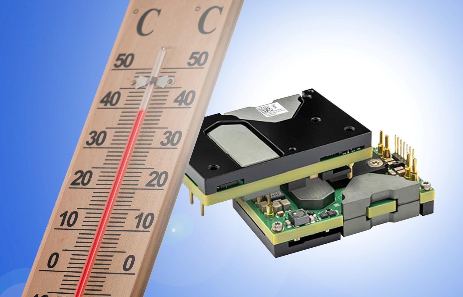
Back in the day, board-mounted DC/DC converters for supply rails in digital systems were so large for their rated power that they were derogatively called ‘bricks’. It was a bit unfair, as they were never as big as even the smaller building bricks, but they certainly took up substantial, valuable board space. One of the main reasons for their size was the need to provide sufficient surface area for cooling, which often relied on convection or incidental system airflow. Over the years, improved efficiency and consequent lower losses have eased the situation, allowing smaller parts, but at the same time, load power demanded has increased dramatically, particularly in typical data center applications, with the emergence of ‘the cloud’, AI and high-performance computing. Additionally, as voltages drop and currents increase, converters need to be fitted ever closer to their loads to avoid voltage and power loss in connections, and this has made size more of an issue with sometimes thousands of CPU connections having to mix in with the power traces. At the same time, this puts the converter in a hotter environment. When the load was 100 W and the DC/DC dissipated 15 W a few inches away, they could be cooled separately and thermal interactions largely neglected, but when the figures are more like 1 kW and 50 W with little physical separation, the DC/DC and load must be treated as thermally inter-dependent.
DC/DC and load must be considered as one thermal system
Taking the DC/DC and load together, cooling can be achieved in a combination of ways, from simple air convection to cold walls and fluid immersion, but typically, forced air is common for cost sensitive commercial and industrial applications. However, there is often no space for a heatsink to be attached to the DC/DC, so the surface from which heat is removed by air flow is limited. It’s therefore common to rely on heat transfer through the converter pins to the circuit board, which anyway has wide copper traces to cope with the high currents typically seen. Air flow then transfers heat from the DC/DC and the surface of the PCB which itself could also be heated by other components.
Things might be relatively simple if heat dissipation in the load and power converters were constant, but modern data processing systems ‘throttle back’ and accelerate tasks to make efficient use of processing capability and minimize average power draw. Voltage rails are ‘dynamically scaled’ to achieve this so DC/DCs not only see wide variation in loads but also other operating conditions – input and output voltages and air temperature. These variations in turn affect the converter efficiency, changing heat levels to be dissipated. In the most ‘finely tuned’ systems, peak loads are not expected to be thermally sustainable over longer periods without exceeding maximum component internal temperatures, so both the load and DC/DC are typically characterized with a continuous and peak load rating, which has to be carefully monitored so as not to exceed critical temperatures. Flex Power Modules’ BMR491 series (Figure 1) is an example of a product rated at 1540 W as a thermal limit, but at 2450 W peak for a limited time, depending on starting temperature.
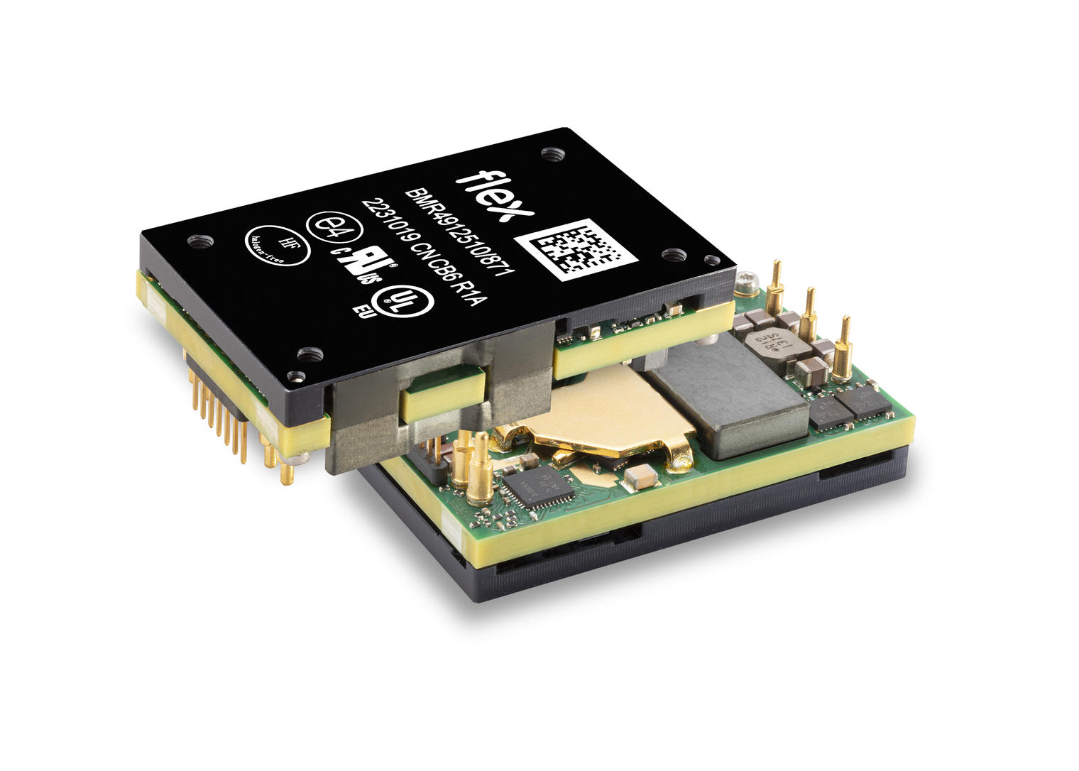
Figure 1: A DC/DC with high peak to continuous power rating - BMR491
Simulation is the way forward
Understandably, with all the interacting variables, traditional analytical methods to predict critical temperatures in components are not practical and simulation is the way forward.
For accurate results, electrical and thermal characteristics of the DC/DC converter must be known and this is provided by the Flex Power Designer tool for the company’s DC/DCs. The software allows a system to be configured from drop-down selections and will calculate individual device and system efficiency, power dissipated and hot-spot temperature from user-specified conditions. Particularly, airflow rate can be defined along with air temperature, PCB thickness, copper coverage and its maximum allowed temperature, which will often be a limiting factor. See example screenshot Figure 2. The tool takes account of the way the device efficiency changes at different temperatures from established test data and will update results ‘on-the-fly’.
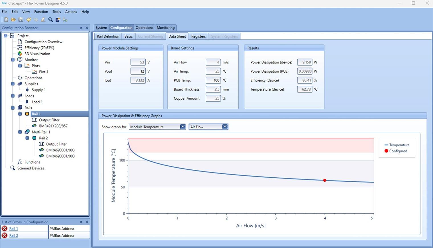
Figure 2: Example screenshot of the Flex Power Designer Tool showing, in this case, DC/DC module hot-spot temperature v. air flow rate
Seeing capability in 3D
While the simulation tool shows actual results under specified conditions, the data sheets also provide traditional power derating graphs, for example with air temperature and flow rate. For this, assumptions must be made about the size and characteristics of any attached heatsink and PCB as well as air flow direction. For a more accurate indication, Flex Power Modules takes this a step further with ‘3D’ representations of derating with specified baseplate and pin temperatures (Figure 3). From qualification data, Flex Power Modules has also accurately characterized their parts for the relationship between these interacting hot-spots and maximum allowable junction temperatures, so that users can be confident that if these values are not exceeded at the given power, maximum utilization of the part without undue stress is achieved.
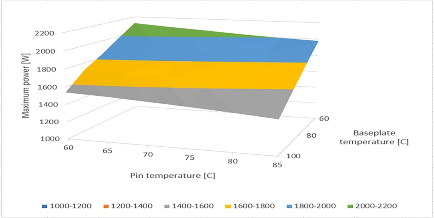
Figure 3: A typical 3D derating graph, for a device within their BMR491 series
Integrating DC/DC thermal simulation with other components
Although DC/DCs might be a major source of heat on a PCB, there will be other components contributing as well, not least those acting as loads on the converter. Their total interaction can be simulated in programs such as FloTherm. Flex Power Modules offers CAD models for their DC/DCs in STEP format, which can be imported into FloTherm through the FloEDA bridge for a full system thermal simulation. The models are finely detailed to include the heat contributing elements and the characteristics of each DC/DC PCB layer, including dielectric and vias. Flex Power Modules provides the power dissipated for each source of heat under various operating conditions and defines the temperature monitor points. As a check, the DC/DC FloTherm model is calibrated against wind-tunnel tests such that simulated temperature rises are typically within 2°C of the measured values.
Peak load effects
Many of Flex Power Modules’ DC/DCs have a peak load capability, for example their BMR313 series, rated at 1 kW continuous and 3 kW peak. With a short transient load, the junction temperature of the device is allowed to reach its maximum rated, typically 150°C or 175°C, and the duration allowed is set by the local thermal capacitance of the power devices. The tools available to avoid device stress are based around local temperature sensors and current measurements, depending on the peak load value. For example, with the BMR313, an overload of 3.4 kW or higher causes a fast hardware shutdown within a few microseconds with a ‘HW_FAULT’ signal generated. Above 2.6 kW, a slower hardware timed shutdown operates within one or two milliseconds with an ‘OC-FAULT’ signal. Up to 1.8 kW, the shutdown is temperature based, with an alert signal generated on a dedicated pin, requesting the load to reduce power if possible. Figure 4 shows the levels and timings.
Figure 4: BMR313 continuous, peak and transient peak protection scheme
The actual junction temperatures reached during peak power events depends naturally on the starting point, and maximum power available with safe operation can be achieved by estimating temperature from current levels and known device characteristics. This is implemented in the BMR350 product for example, where current is monitored and the signal filtered with an ‘Exponential Moving Average’ (EMA) method. This can be extended with a ‘dual EMA’ scheme with different weightings to additionally emulate the effects of varying cool-down periods between peak load pulses.
A comprehensive set of design tools for maximum performance and minimum stress
The combination of Flex Power Designer software, FloTherm models and hardware protection provides a tool set enabling rapid and efficient design, modelling, and monitoring of complex power conversion systems. Choosing modules from the Flex Power Modules range, thermal performance can be optimized at the DC/DC and system level for minimum stress while achieving maximum power density and value. Visit https://flexpowermodules.com to explore the products and design tools available.