What’s driving the need for different input/output ratios of DC/DCs?
Introduction
The most common power conversion function is from AC mains to low voltage DC. As the application power levels increases, as seen in AI and cloud computing hardware, the gap between input and output widens. The largest industrial or data center systems might have 400V three-phase AC input and a final sub-1V DC output for a processor or similar complex IC. How to do this conversion efficiently has been a topic since at least the 1980s and over the years, techniques have come and gone as power levels and technology have changed and evolved.
In end-to-end power conversion there are multiple choices
For sure, the AC input has to be rectified first with the statutory need for power factor correction and ‘universal’ AC input then results in a DC rail of around 400V, for example, for single phase supply. The challenge is then to convert this down to the application voltage with minimum distribution and conversion losses. There are other considerations as well though, safety isolation must be included for any voltage over 60V, EMI levels must be controlled, cabling and converter costs must be minimized and the end voltage must be accurate and sometimes adjustable. Increasingly, power density is a concern where the converters used must be compact to fit close to the load yet able to be cooled adequately.
The preferred solution has been to generate one or more intermediate buses for distribution at a higher voltage, where for a given power, ohmic losses are less, for example, 16x lower for 48V compared with 12V because current is one quarter. This is followed by down-conversion to the final voltage with further ‘Point of Load’ (PoL) DC-DC converters, VRMs (Voltage Regulator Modules) or increasingly IPSs (Integrated Power Stages) which combine so called smart power stages together with the necessary output inductor and additional components. There are now choices to be made – what bus voltage(s) is optimum, which stages need to be isolated and which stages need to be regulated?
The initial AC-DC stage to generate the first rack bus voltage must be isolated to meet safety standards but after that, if the voltages are below 60V, isolation is for functional reasons; to break ground loops, ease EMI problems and to provide a way to drop voltage in a large ratio through the transformer turns. 48V with its tolerances is therefore a good choice and a suitable rail for battery back-up. On system boards, PoL converters in the past were only acceptably efficient with a low input-output voltage differential with a narrow input range, so it was typical to use a 4:1 ‘intermediate bus converter’ (IBC) with a regulated 12V output derived from 48V with isolation as power for the PoLs, which might at the time have only needed to provide 5V or 3.3V. This type of IBC has limited efficiency however and it was then appreciated that it did not necessarily need regulation as the 48V input was relatively stable. As long as the PoLs could accept some input variation the IBC could become a simple fixed ‘ratio converter’ which is much more efficient and has some benefits in dynamic performance. Some schemes such as in our BMR492 have a ‘hybrid regulated ratio’ and are fixed ratio up to a certain input voltage then regulation cuts in, to limit the overall output voltage variation while keeping overall efficiency high. Similarly, if isolation is omitted, high efficiency ‘switched capacitor’ circuits can be used as an IBC, such as the Flex Power Modules’ BMR310, but again restricted to a fixed ratio which in this case must be an integer (4:1). Alternatively, non-isolated and unregulated parts such as Flex Power Modules' BMR313/314, using their ‘resonant DC transformer (DCX)’ topology can achieve over 97% efficiency at 1kW rating with a 4:1 conversion ratio.
PoL converters are increasingly efficient with wider inputs and step-down ratios
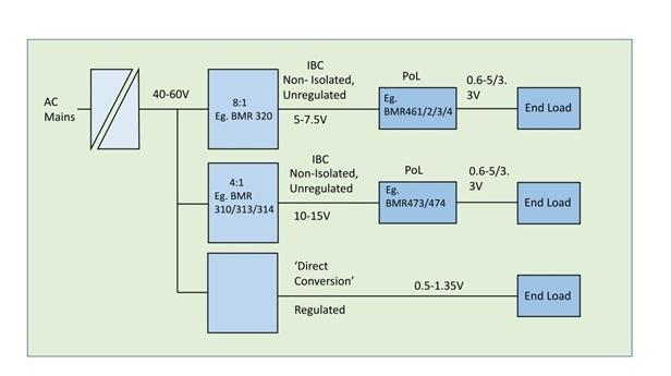
Fortunately, advances in PoL topology and semiconductor switches have allowed them to become more efficient even with wider input ranges and high step-down ratios to the sub-1V levels now seen, so the system designer now has a wider choice. For example, an IBC with an input range of 40V – 60VDC can output either 10-15VDC (4:1); 8-12VDC (5:1); 6.7-10VDC (6:1); 5-7.5VDC (8:1) or 4-6VDC (10:1), the higher IBC voltages can result in less current and easier PCB layout, but lower IBC voltages can result in better efficiency operation for the downstream PoLs, VRMs or IPSs. These can then be chosen with an input range to match which exhibits best efficiency for a given load. An example pairing might be the 8:1 ratio 400W BMR320 and the forthcoming BMR515 16-phase integrated power stage optimized for a 4.5-7.5V input. This pairing could deliver up to 670A at voltages of 0.5-0.9V to a GPU for example, and be able to deliver peak currents for short durations too.
As end-load power consumption increases further, techniques can be used to keep efficiency high. For example, multiphase PoL buck converters can have optimized efficiency over a wider load range and end devices with particularly high-power consumption can have their own ‘power island’ with a dedicated two-stage intermediate bus, tailored for best efficiency. The efficiency of PoLs can also be optimized with MOSFET switches that have just the minimum voltage rating required, as on-resistance naturally reduces with lower voltage-rated devices, all things being equal. MOSFET manufacturers have recognized this fact and are increasingly offering 15V devices which align with lower bus voltages and as a bonus are able to switch at higher frequency, reducing inductor and capacitor sizes and internal losses. This can free-up PCB area for use of multi-phase PoLs with their own efficiency gains.
A holistic view is needed for best overall system efficiency
In some specific scenarios, an analysis of efficiency and required performance can show that ‘direct conversion’ from 48V to an output as low as 0.5V can yield higher efficiency and lower system size and cost than the combination of IBCs and PoLs, the Flex Power Modules’ BMR482 is a good example.
Latest technology advances from Flex Power Modules have widened the choices available to system designers who can now take a ‘holistic’ system view and pick where, and if isolation and regulation are needed, to achieve the best overall efficiency and functionality.